Fluorescent task lamp with optimized bulb alignment and ballast

a task lamp and bulb alignment technology, applied in the field of hand-held fluorescent lighting units, can solve the problems of inconvenient operation of incandescent light bulbs, bulb to get too hot to touch, and even use close to one's person, etc., and achieve the effect of improving the utility of task lamps in many work situations

Inactive Publication Date: 2007-04-10
BAYCO PRODS
View PDF8 Cites 80 Cited by
  • Summary
  • Abstract
  • Description
  • Claims
  • Application Information

AI Technical Summary

Problems solved by technology

It is well known that incandescent light bulbs are not economical to operate because much of the electrical energy used by the task light is converted to heat.
The tungsten filament in a typical 100 Watt incandescent bulb causes the bulb to get too hot to touch, or even use close to one's person.
Moreover, the relatively fragile nature of the tungsten filament impairs the utility of a task lamp in many work situations.
However, fluorescent bulbs require a relatively high voltage to initiate the plasma state.
Unless the current is limited after ignition of the bulb, the tube will draw excessive current and damage itself and / or the supply circuit.
For typical installed lighting fixtures using non-self-starting bulbs and operating at 120 VAC, 60 Hz, the wire gauge, the number of turns in the coils, and size of the magnetic core result in a large and heavy ballast component.
Miller et al. thus has the disadvantages of relatively high component count, and is not capable of driving non-self-starting or self-starting bulbs from the same ballast circuit.
The portable fluorescent lamp disclosed by Miller et al. further appears to lack the ability to withstand mechanical impacts that frequently occur during the use of task lamps.

Method used


Image

  • Fluorescent task lamp with optimized bulb alignment and ballast
  • Fluorescent task lamp with optimized bulb alignment and ballast
  • Fluorescent task lamp with optimized bulb alignment and ballast

Examples


Embodiment Construction

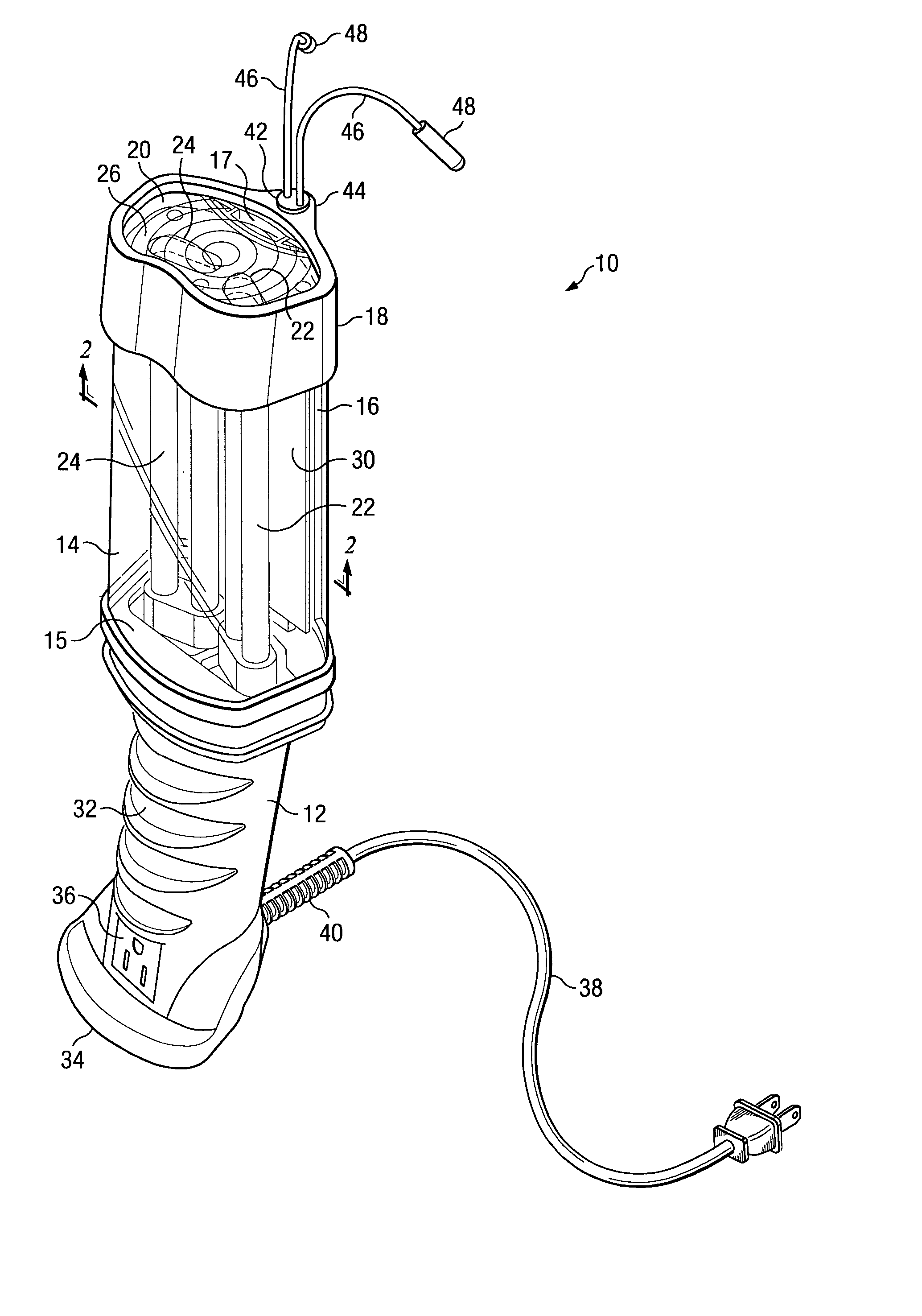
[0020]In the following description, structures bearing the same reference numbers in the various figures are alike. Referring to FIG. 1 there is illustrated a pictorial perspective view of a fluorescent task lamp 10 according to one embodiment of the present invention, as viewed from a perspective above and to the left side of the task lamp 10. The illustrative task lamp 10 is designed to be conveniently held in a user's hand or supported by built-in, adjustable hooks, and is approximately 13 inches in length, excluding the extendable hooks and the line cord. The task lamp 10 includes a housing 12, a clear lens body 14, an elongated spine 16 extending upward from the open end of the housing 12, and a flexible cap 18 that fits over the combination of the upper, closed end 20 of the lens body 14 and the distal end 17 of the elongated spine 16. The distal end 17 of the elongated spine 16 is barely visible in FIG. 1 through the closed end 20, but see also FIGS. 7 and 8. Further, the clo...


PUM


Abstract

A handheld fluorescent task lamp comprising a housing assembly having a housing and a tubular lens body enclosing compact fluorescent bulbs, an elongated spine configured for slidingly supporting the lens body, and a resilient bulkhead for cushioning the compact fluorescent bulbs in the lens body; an electronic ballast circuit within the housing comprising a power supply, a self-starting electronic driver circuit operable to start and run at least first and second CFL bulbs; a bulb accommodation circuit that enables operation of the electronic ballast circuit with either starter type or non-starter type and regardless whether one or both CFL bulbs are connected to the driver circuit; and an illumination assembly, wherein the CFL bulbs are oriented with respect to each other such that an enhanced forward emission field is provided.

Description

CROSS REFERENCE TO RELATED APPLICATIONS[0001]This patent application is related to copending U.S. patent application Ser. No. 10 / 836,482, filed Apr. 20, 2004 and entitled “Portable Fluorescent Task Lamp.BACKGROUND OF THE INVENTION[0002]1. Field of the Invention[0003]The present invention generally relates to handheld lighting units and more particularly to handheld fluorescent lighting units having an improved electronic ballast, enhanced forward illumination, resistance to mechanical impact, and accommodation of one or more of various types of fluorescent bulbs.[0004]2. Description of the Prior Art[0005]Portable, hand-held drop lights or task lamps utilizing an incandescent bulb and powered by AC line current, typically 120 Volts AC, 60 Hz, allow the user to provide light where installed light fixtures do not provide adequate coverage. However, incandescent bulbs as the light source in task lamps have several disadvantages. It is well known that incandescent light bulbs are not eco...

Claims


Application Information

Patent Timeline
Patent Type & Authority Patents(United States)
IPC IPC(8): F21L19/00
CPCF21L14/026F21V13/045F21V15/01F21V15/04F21V17/104F21V19/009F21V19/0095F21V23/02F21Y2103/025F21Y2103/37
Inventor BAYAT, BIJANNEWTON, JAMESPROBASCO, MAX ALAN
Owner BAYCO PRODS
Why Eureka
Try Eureka