Unlock instant, AI-driven research and patent intelligence for your innovation.

Borehole marking devices and methods

a technology for drilling holes and marking devices, applied in the field of drilling holes marking devices and methods, can solve the problems of increasing the complexity of oil wells, affecting geosteering, and affecting geosteering, and achieve the effects of dramatic geosteering errors

Active Publication Date: 2007-04-17
HALLIBURTON ENERGY SERVICES INC
View PDF39 Cites 13 Cited by
  • Summary
  • Abstract
  • Description
  • Claims
  • Application Information

AI Technical Summary

Benefits of technology

The present invention relates to a method for accurately locating devices in a subterranean formation. The invention involves placing markers at known reference points in a borehole to reduce uncertainty in positioning the devices. By using known reference points, the invention aims to reduce surveying errors that tend to accumulate as the borehole is drilled. The invention can be used in geosteering, a technique used to direct drilling in subterranean formations. The invention can also be used in monitoring the progress of drilling or investigation of a well. Overall, the invention improves the accuracy of locating devices in a subterranean formation.

Problems solved by technology

The search for oil and other hydrocarbons has led in recent years to more and more complex oil wells.
Geosteering can be adversely affected if the natural markers are not where they are predicted to be.
The effect of such errors on geosteering can be dramatic.
This combination of factors may produce an error of 90 feet, which might be larger than the thickness of a formation of interest.
Any measurement error of this magnitude could easily cause the perforation to completely miss the location of a target formation.

Method used


Image

  • Borehole marking devices and methods
  • Borehole marking devices and methods
  • Borehole marking devices and methods

Examples


Embodiment Construction

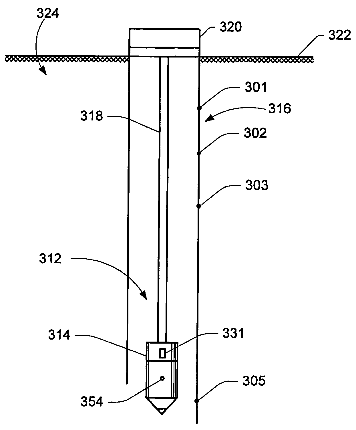
[0016]The present invention reduces the uncertainty of locating a bit, a tool or other devices or points of interest, for example, a bed boundary, in a wellbore by placing one or more markers at known reference points in a borehole rather than using a single reference point at the surface of the earth. By using known reference points within the borehole, it is possible to reduce surveying errors which tend to accumulate.

[0017]Conventionally, outputs from real time downhole data are correlated with expected outputs based either on offset wells or on a vertical section of wells through the same zones with the same pilot hole. The identification of geological markers with depth is imprecise because it is difficult to predict the location of these markers with certainty based on logs obtained, for example, from offset wells.

[0018]Exemplary problems that can arise when using this technique are illustrated in FIG. 1 where subterranean formations are divided into three different zones: zon...


PUM


Abstract

To reduce the surveying error in a wellbore, the creation of several reference points within a borehole is carried out by physically placing borehole markers in the borehole casing, the borehole wall or in the formation itself, and providing an accurate reference of the marker locations by either storing information specific to the borehole markers inside or on the marker itself, or assigning an identification number to the marker and storing the information relating to that identification number remotely in a database. The borehole markers may contain an electronic module which includes a microcircuit, a transponder dedicated to the transmission and reception of data to / from a detector placed on a wireline tool, a drill string or a coiled tubing. The detectors may have an additional role of interrogating the electronic modules.

Description

FIELD OF THE INVENTION[0001]The present invention pertains generally to the field of equipment and operations utilized in investigating subterranean formations. More particularly, the invention relates to apparatus and methods for locating a position in a borehole using embedded borehole markers. The invention may be used to measure the location of a device in a borehole using borehole markers embedded in a borehole casing, a borehole wall or a particular formation.BACKGROUND OF THE INVENTION[0002]The search for oil and other hydrocarbons has led in recent years to more and more complex oil wells. Frequently, techniques such as geosteering are used to direct a well to a precise location in the subsurface.[0003]Geosteering often relies on natural markers, such as formation boundaries, to confirm that the borehole is proceeding as planned. The formation boundaries are predicted from seismic surveys or from nearly offset wells. Geosteering can be adversely affected if the natural marke...

Claims


Application Information

Patent Timeline
Patent Type & Authority Patents(United States)
IPC IPC(8): E21B47/09E21B47/00
CPCE21B47/00E21B47/09
Inventor DUDLEY, JAMES H.RODNEY, PAUL F.
Owner HALLIBURTON ENERGY SERVICES INC