Prying tool for dislodging concrete forms from poured concrete walls

Inactive Publication Date: 2007-04-17
SIMMONS MARK
View PDF5 Cites 3 Cited by
  • Summary
  • Abstract
  • Description
  • Claims
  • Application Information

AI Technical Summary

Benefits of technology

[0010]It is an object of this invention to separate forming systems from the hardened and set concrete with a minimum of damage to the concrete or chipping of the concrete.
[0011]It is another object of this invention to accomplish the foregoing in a faster and easier manner than can be accomplished without using the prying tool of this invention.
[0012]It is another object of this invention to separate forming systems from set concrete with reduced physical force, and to reduce injuries such as wrenching one's back in straining to remove the form from the set concrete.
[0013]It is another object of this invention to accomplish the foregoing by the use of the prying tool of this invention which can be easily and inexpensively manufactured.

Problems solved by technology

After pouring of the concrete, the forms must be dislodged from the set concrete, which task has not heretofore been able to be easily carried out without encountering considerable difficulties.
Firstly, the workers are obliged to work overhead which requires a very taxing physical effort.
Secondly, the dislodging process has been relatively slow and time-consuming since there has heretofore been no highly effective manner of engaging the forms with a pry tool.
However, the lip edges of the forms are not overly large to allow effective engagement of a pry bar and pry bars often cause damage to the finished concrete walls.
The resulting difficulties encountered by the construction workers renders this particular task rather labor intensive and time consuming.

Method used


Image

  • Prying tool for dislodging concrete forms from poured concrete walls
  • Prying tool for dislodging concrete forms from poured concrete walls
  • Prying tool for dislodging concrete forms from poured concrete walls

Examples


Embodiment Construction

[0026]It should be understood that the following is a detailed description of the invention and that numerous changes to the disclosed embodiments can be made in accordance with the disclosure herein without departing from the spirit or scope of the invention. Rather, the scope of the invention is to be determined only by the appended claims and their equivalents.

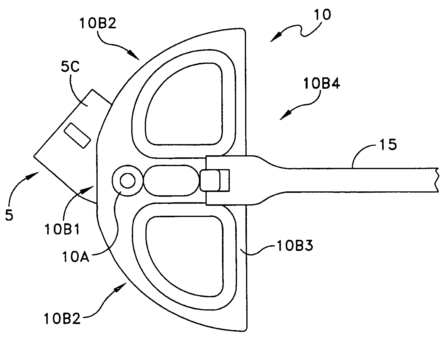
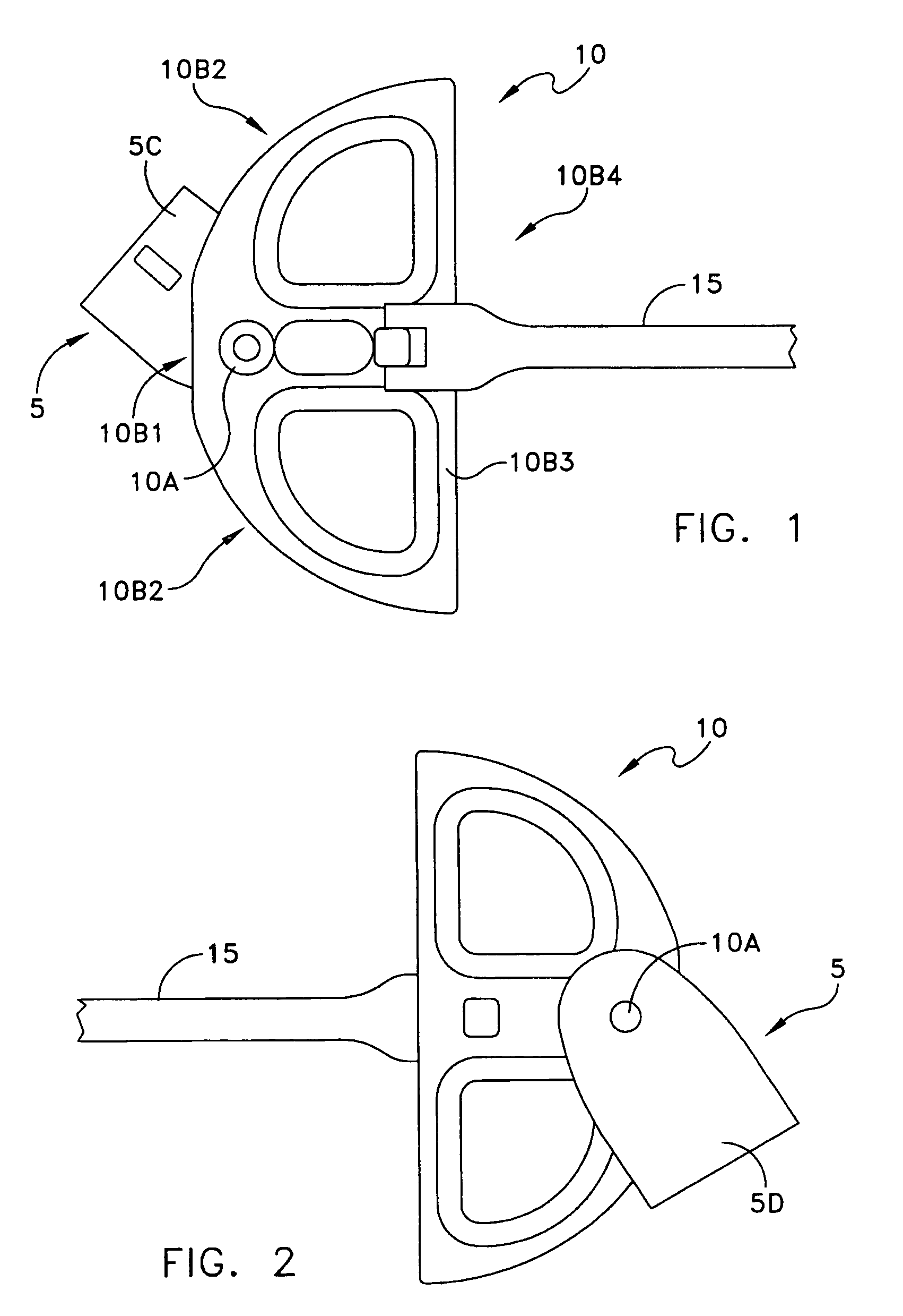
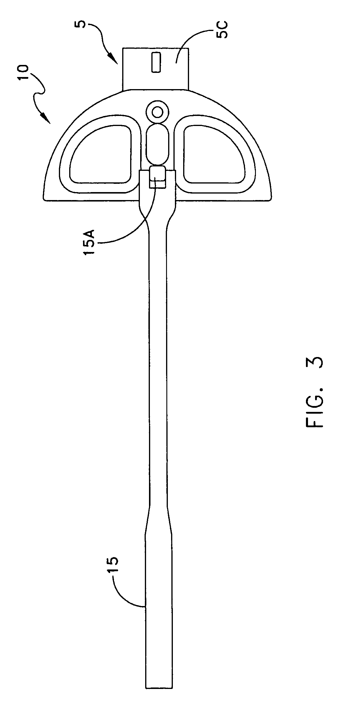
[0027]Referring to FIGS. 1–4, a prying tool is disclosed comprising a fulcrum assembly 5, a pivoting leveraging member 10, and a handle member 15. Fulcrum assembly 5 includes a first side surface 5C and a second side surface 5D. First side surface 5C includes at one end a protuberance 5A and at the opposite end an extension section 5B extending outward at a right angle from the opposite end. Leveraging member 10 includes at one end a pivoting engagement means 10A and at the opposite end a handle extending outward therefrom. Handle member 15 is connected to leveraging member 10 through a socket type connection 15A.

[0028]Hand...


PUM


Abstract

The pry tool of the present invention is utilized for dislodging concrete forms from set concrete. It includes a fulcrum assembly and pivoting leveraging member in operative juxtaposition to the fulcrum assembly. One end of the fulcrum assembly engages a first single concrete form member connecting slot and the opposite end of the fulcrum assembly connects to a pivoting leveraging member. The leveraging member is parallel and set off from the fulcrum assembly in direct alignment with a second adjacent concrete form. The leveraging member is hand manipulated to exert force against the second adjacent concrete form forcing the form inward into the concrete wall. This causes a leveraging action with the engaged end of the fulcrum assembly forcing the first concrete form outward away from the concrete wall and thereby separating the form from the wall.

Description

BACKGROUND OF THE INVENTION[0001]1. Field of the Invention[0002]This invention concerns pry tools and more particularly pry tools especially adapted for dislodging concrete forms from set concrete.[0003]2. Description of the Prior Art[0004]Concrete shapes, such as walls and the like, are often poured on the job site with the aid of forms made of steel or the like. The forms are constructed by placing the form walls side by side, passing tie rods between the form walls, and exerting a pulling force on each tie rod to draw the forms towards one another. The tie rods are inserted through a series of parallel connecting slots that are punched through the form walls. A plurality of parallel rows of forms in end to end alignment are provided to make up a complete concrete form.[0005]After pouring of the concrete, the forms must be dislodged from the set concrete, which task has not heretofore been able to be easily carried out without encountering considerable difficulties.[0006]Firstly, ...

Claims


Application Information

Patent Timeline
IPC IPC(8): B66F15/00
CPCB66F15/00E04G19/00
Inventor SIMMONS, MARK
Owner SIMMONS MARK
Why Eureka
Try Eureka