Composite sandwich with improved ballistic toughness

Inactive Publication Date: 2006-05-04
UNITED TECH CORP
View PDF11 Cites 70 Cited by
  • Summary
  • Abstract
  • Description
  • Claims
  • Application Information

AI Technical Summary

Benefits of technology

[0008] Accordingly, it is an object of the present invention to provide an extremely light and stiff composite struct

Problems solved by technology

If a fan blade fails and is released the fragments become high-energy projectiles.
Interaction of the fabric with the blades causes additional damage.
This however increases the diameter o

Method used


Image

  • Composite sandwich with improved ballistic toughness
  • Composite sandwich with improved ballistic toughness
  • Composite sandwich with improved ballistic toughness

Examples


Embodiment Construction

)

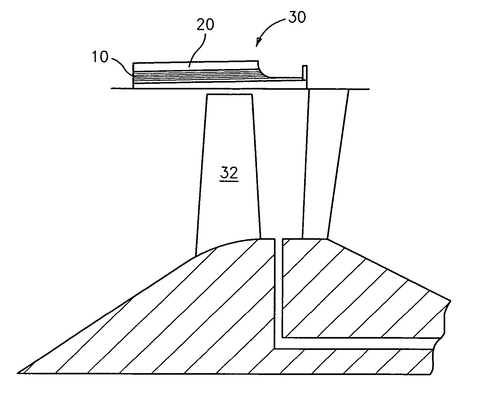
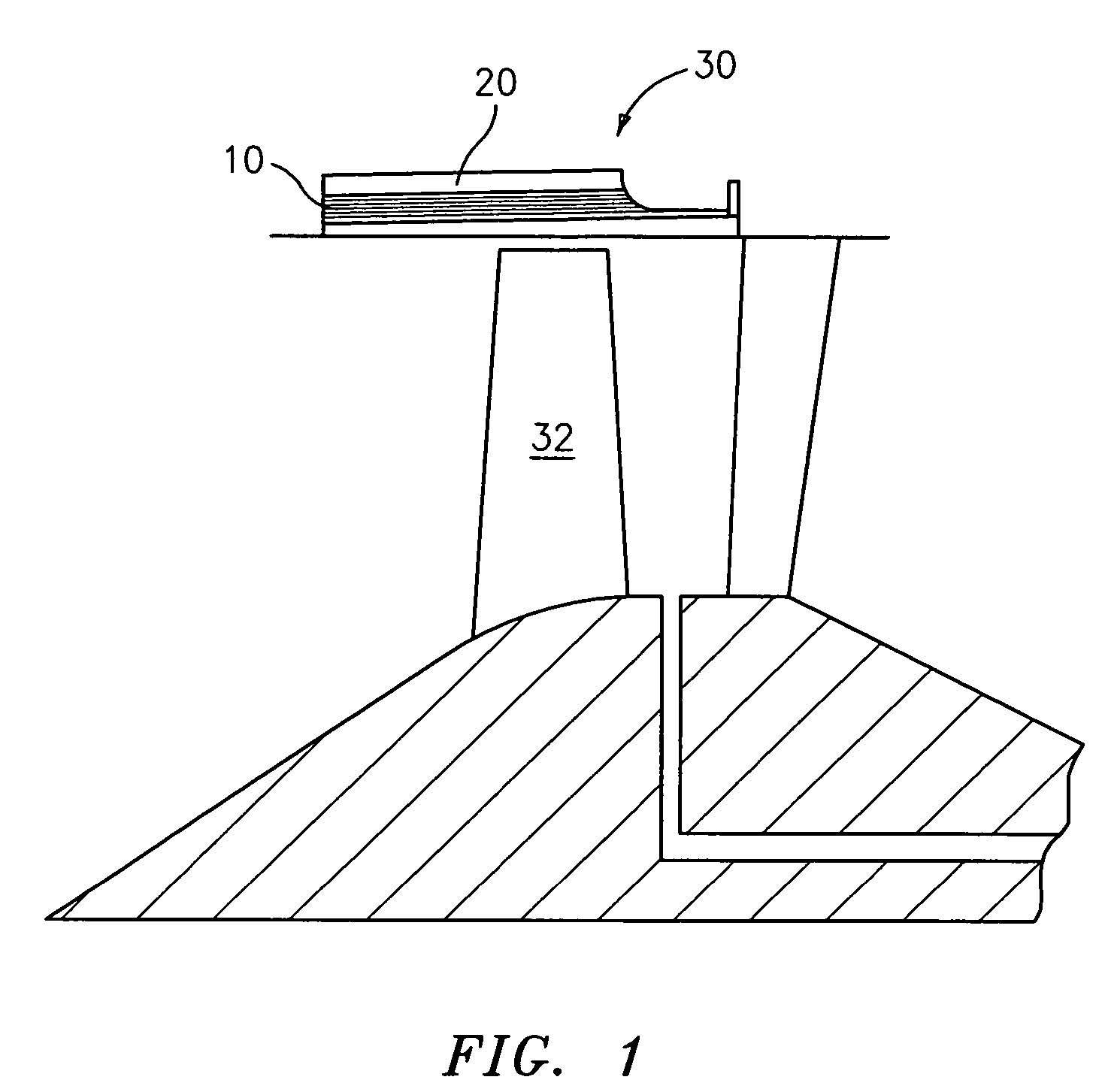
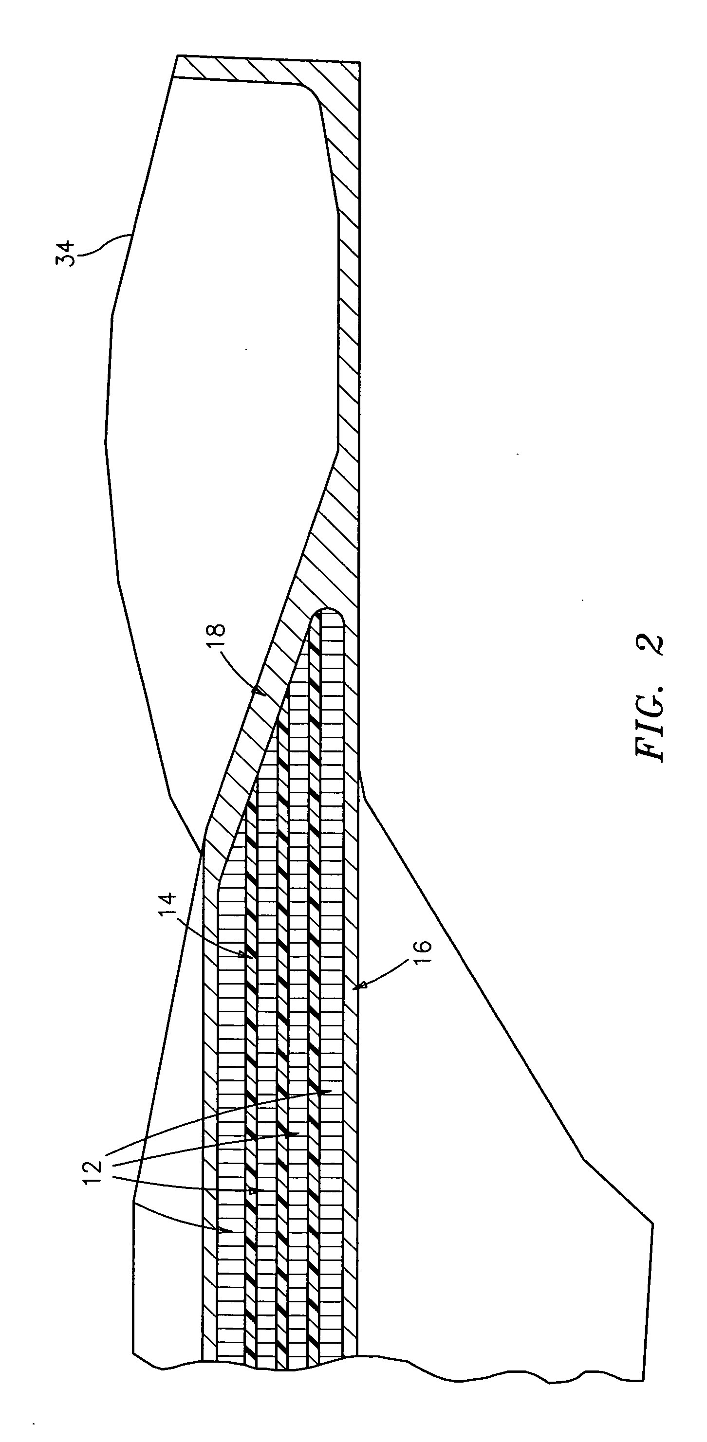
[0015]FIGS. 1-3 illustrate a composite structure 10 in accordance with the present invention. The composite structure 10 has a plurality of core layers 12 and a plurality of inner ply layers 14 with the inner plies 14 being located between adjacent ones of the cores 12. Each inner ply layer 14 may be joined to adjacent ones of the cores 12 by any suitable adhesive known in the art, such as a scrim supported adhesive. A scrim supported adhesive is a preferred adhesive because it will prevent galvanic reaction between the cores 12 and any carbon structure used in the layers 14.

[0016] The cores 12 may be formed from a honeycomb material or a foam material. A suitable honeycomb material is one formed from aluminum or an aluminum alloy. The walls of the honeycomb material may have any suitable thickness.

[0017] The inner plies 14 are each preferably formed from an organic matrix composite (OMC). OMC's are made from fibers that provide a high tensile strength and a matrix material that ...


PUM

PropertyMeasurementUnit
Thicknessaaaaaaaaaa
Thicknessaaaaaaaaaa
Forceaaaaaaaaaa

Abstract

A composite structure having improved ballistic toughness and suitable for use in a fan containment case is provided. The composite structure includes a plurality of core layers, a plurality of inner plies position between adjacent ones of the core layers, each of the inner plies being formed from an organic matrix composite, an inner skin located adjacent an innermost one of the core layers, and an outer skin located adjacent an outermost one of the core layers. In a preferred embodiment, the core layers are formed from a honeycomb material made from aluminum or an aluminum alloy.

Description

BACKGROUND OF THE INVENTION [0001] The present invention relates to gas turbine engines, and, more particularly to a composite structure within the fan region for containing released blade fragments of a gas turbine engine. [0002] Gas turbine engines have large fans at the forward end that rotate at high speeds. If a fan blade fails and is released the fragments become high-energy projectiles. These fragments can weigh as much as seven kilograms and can travel at speeds about 9.30 meters per second. It is critical to contain these blade fragments and to retain the structural integrity of the casing that surrounds the fan and its blades. [0003] A typical containment structure is shown in U.S. Pat. No. 4,490,092 to Premont. A support structure has “C” shaped stiffeners between inner and outer shrouds. This structure surrounds the fan and has multiple layers of woven KEVLAR ballistic fabric. This fabric is wound under tension and serves to resiliently contain blade fragments passing th...

Claims


Application Information

Patent Timeline
IPC IPC(8): B32B3/12B32B27/32
CPCF01D21/045F02K3/04Y02T50/672F05D2220/327F05D2250/283Y10T428/24149F05D2300/44F05D2300/603F05D2300/612F05D2300/614F05D2300/433Y10T428/31938Y02T50/60F01D25/24F01D25/26F01D21/00
Inventor HORNICK, DAVID CHARLESTREAT, ROBERT KENNETHFOOSE, ANDREW
Owner UNITED TECH CORP
Why Eureka
Try Eureka