High quantum efficiency x-ray detector for portal imaging

a detector and portal imaging technology, applied in radiation measurement, instruments, electrical equipment, etc., can solve the problems of not being able to design a practical detector of this kind, megavoltage x-rays, and not yet ideal systems for portal imaging applications, and achieve the effect of increasing the probability of x-ray absorption

Inactive Publication Date: 2007-04-17
SUNNYBROOK HEALTH SCI CENT
View PDF8 Cites 5 Cited by
  • Summary
  • Abstract
  • Description
  • Claims
  • Application Information

AI Technical Summary

Benefits of technology

[0008]the electrically conductive plate substrate being made of a high density metal and the at least one detector element being oriented with respect to a source of x-rays so that the electrically conductive plate substrate is aligned in a direction of a flux of incident x-rays in order for x-rays entering the upper edge of the electrically conductive plate substrate to travel through a length of the electrically conductive plate substrate thereby increasing the probability of absorption of the x-rays by the electrically conductive plate substrate;

Problems solved by technology

They are, however, not yet ideal systems for portal imaging application (using megavoltage x-rays) due to the low x-ray absorption, i.e., low quantum efficiency (QE), which is typically on the order of 2–4% as compared to the theoretical limit of 100%.
However, how to design a practical detector of this kind remained open.

Method used


Image

  • High quantum efficiency x-ray detector for portal imaging
  • High quantum efficiency x-ray detector for portal imaging
  • High quantum efficiency x-ray detector for portal imaging

Examples


Embodiment Construction

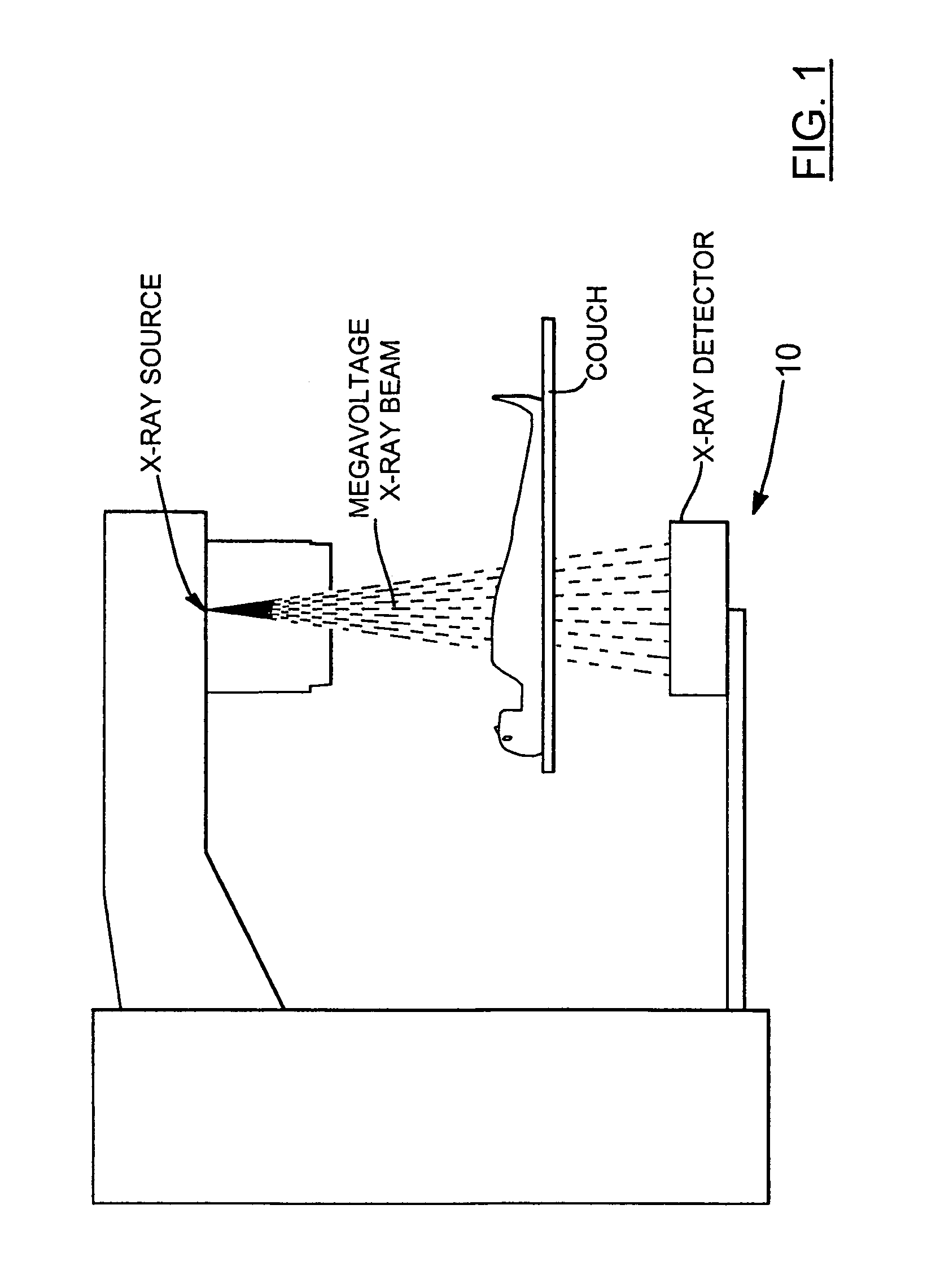
[0022]Referring to FIG. 1, an objective of the present invention is to provide a practical design of a megavoltage x-ray detector with both high QE and high resolution to replace current low QE x-ray detectors used in radiotherapy. The x-ray beam emitted from a linear accelerator (Linac) is of high energies and typically ranges from 1MV to 25MV. The x-ray beam is typically of cone shape. The maximum size of the x-ray beam (also referred to as the field size) at the distance 100 cm away from the x-ray source is typically 40 cm×40 cm. The distance from the detector to the x-ray source can be variable and typically range from about 100 cm to about 240 cm. Thus, to image the whole x-ray beam, an area detector with a large field of view (from ˜40 cm×40 cm up to ˜100 cm×100 cm) is preferred. The size of the detector, however, depends on the end applications and could be small if it is used in a laboratory for, e.g., imaging small animals and larger for imaging humans as shown in FIG. 1.

[0...


PUM


Abstract

The present invention provides a practical design of a megavoltage x-ray detector with both high quantum efficiency (QE) and high resolution. The x-ray detector disclosed herein has a QE that can be an order of magnitude higher than that of current flat panel systems and yet has a spatial resolution equivalent to that of current flat panel systems used for portal imaging. The x-ray detector includes a large number of micro-structured electrically conducting plates, packed together with thin spacers placed between neighboring plates with the micro-structured plates oriented to be parallel to the incident x-rays in operation. Each plate includes an electrically conductive substrate with a first planar surface, elongate electrically conductive strip electrodes separated from each other with strip spacers placed in between and sitting on an insulating layer interposed between the first planar surface of the electrically conductive substrate and the strip electrodes. A power supply applies a bias voltage between each electrically conductive substrate and the electrically conductive strip electrodes, whereby x-rays absorbed in the conductive substrate generates high energy electrons which produce ions in an ionization medium located in spaces between the conductive substrate and the electrically conductive strips. A detector detects an electrical current generated in the electrically conductive strip electrodes and a 2D active readout matrix is coupled to the detector.

Description

CROSS REFERENCE TO RELATED U.S. PATENT APPLICATION[0001]This patent application is a Divisional application of U.S. patent application Ser. No. 10 / 679,512 entitled “HIGH QUANTUM EFFICIENCY X-RAY DETECTOR FOR PORTAL IMAGING” filed on Oct. 7, 2003 now U.S. Pat. No. 7,030,386 in the name of the same inventors which claims the benefit of, U.S. provisional patent application Ser. No. 60 / 416,229 filed on Oct. 7, 2002, entitled HIGH QUANTUM EFFICIENCY X-RAY DETECTOR FOR PORTAL IMAGING, which is incorporated herein in its entirety.FIELD OF THE INVENTION[0002]This invention relates generally to improved electronic portal imaging devices (EPIDs) used in radiation therapy, and more particularly the present invention relates to high quantum efficiency (QE) x-ray detectors for portal imaging applications including megavoltage cone beam computed tomography (MVCT).BACKGROUND OF THE INVENTION[0003]Recently developed flat panel detectors have been proven to have a much better image quality than conv...

Claims


Application Information

Patent Timeline
Patent Type & Authority Patents(United States)
IPC IPC(8): G01T1/24G01N23/04G01T1/29
CPCG01T1/2928G01T1/2935
Inventor PANG, GEORDI GENDIROWLANDS, JOHN ALAN
Owner SUNNYBROOK HEALTH SCI CENT
Why Eureka
Try Eureka