Master-slave critical conduction mode power converter

a power converter and critical conduction mode technology, applied in the direction of electric variable regulation, process and machine control, instruments, etc., can solve the problems of power loss, complex implementation, and difficulty in creating noise-free output power without introduction, and achieve excellent input current ripple cancellation, good current sharing, and minimal interference

Active Publication Date: 2007-04-17
MYPAQ HLDG LTD
View PDF15 Cites 29 Cited by
  • Summary
  • Abstract
  • Description
  • Claims
  • Application Information

AI Technical Summary

Benefits of technology

[0022]In some applications, including power factor correction (PFC) front ends intended for use in power supplies with output power in excess of 300 watts, a power supply system with the following features is desired: good current sharing over the entire range of the input voltage, variable frequency operation, excellent input current ripple cancellation and minimal interference with input power system. The present invention provides a system with these desirable characteristics and with an improved simplicity and ease of manufacture. Further, the present invention avoids the use of bulky and inefficient components, such as sense resistors, present in many prior art devices.
[0024]In another aspect, the present invention utilizes a local voltage controlled oscillator (VCO) in the triggering. In this embodiment, the switch-on of the master power source is locked to the VCO. The frequency is controlled to be the same frequency of the master power source. Further, the VCO has a symmetric output waveform. The slave power source is triggered to the falling edge of the VCO output, which is substantially 180° out of phase with the rising edge (which is in phase with the switch-on of the master power source). Hence, the switch-on of the slave power source will be substantially 180° out of phase with the switch-on of the master power source. This scheme minimizes both input and output ripple currents.

Problems solved by technology

Several issues arise in the construction of power converters.
The most problematic of these is the difficulty of creating noise-free output power without introducing noise into the input power.
Conventional techniques directed toward this problem are well known, but complicated and expensive to implement.
Conventional power converters introduce periodically varying components of the input current and can cause power loss.
In addition, prior art power converters typically do not appear as a simple resistive load to the power input.
A resulting high level of current in the switch M can cause excessive power dissipation and premature failure of the switch M. Because this high level of current occurs each time the switch M is cycled, the switching frequency is limited.
While this preservation of current allows a converter to attain both less lossy switching and improved efficiency over a CM converter, it unfortunately introduces high ripple into both input and output current.
Further, since the components of the two power sources are not identical, slight phase differences naturally occur.
Unfortunately, because the duty cycles of the two power sources are not always 50%, the phases are not always fully opposite.
Furthermore, the device of FIG. 7 loses phase lock at the limits of the regulation loop, which results in a complete loss of input ripple current cancellation, and can result in audible noise emanating from the device.

Method used


Image

  • Master-slave critical conduction mode power converter
  • Master-slave critical conduction mode power converter
  • Master-slave critical conduction mode power converter

Examples


Embodiment Construction

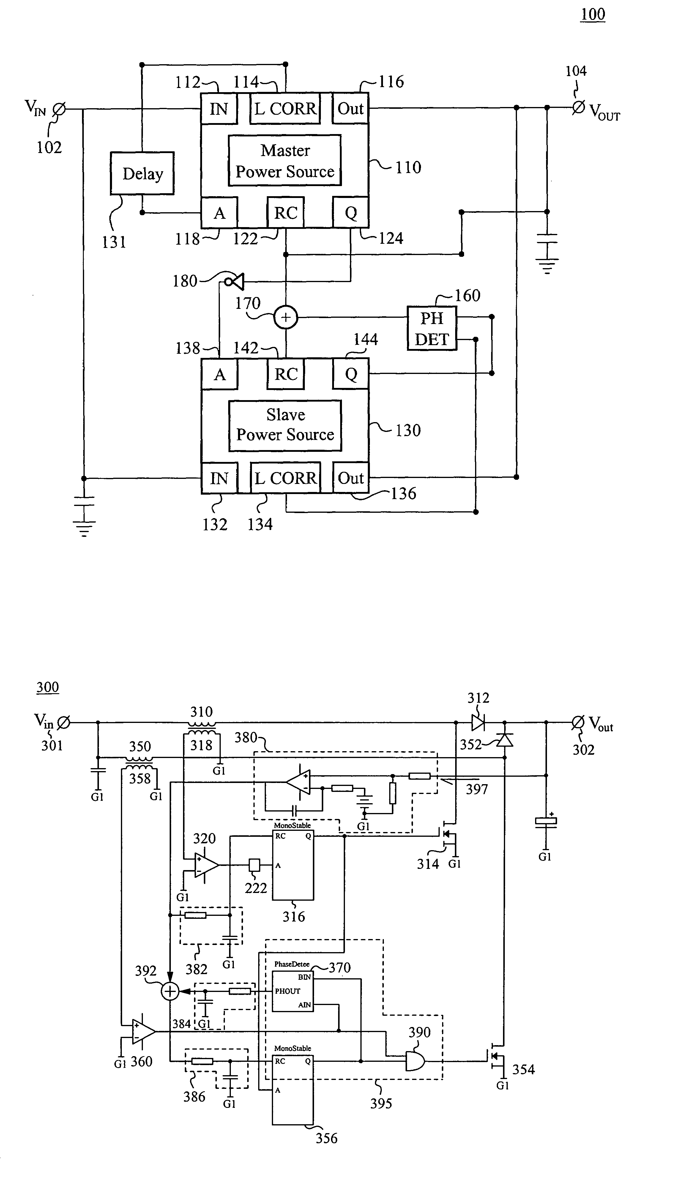
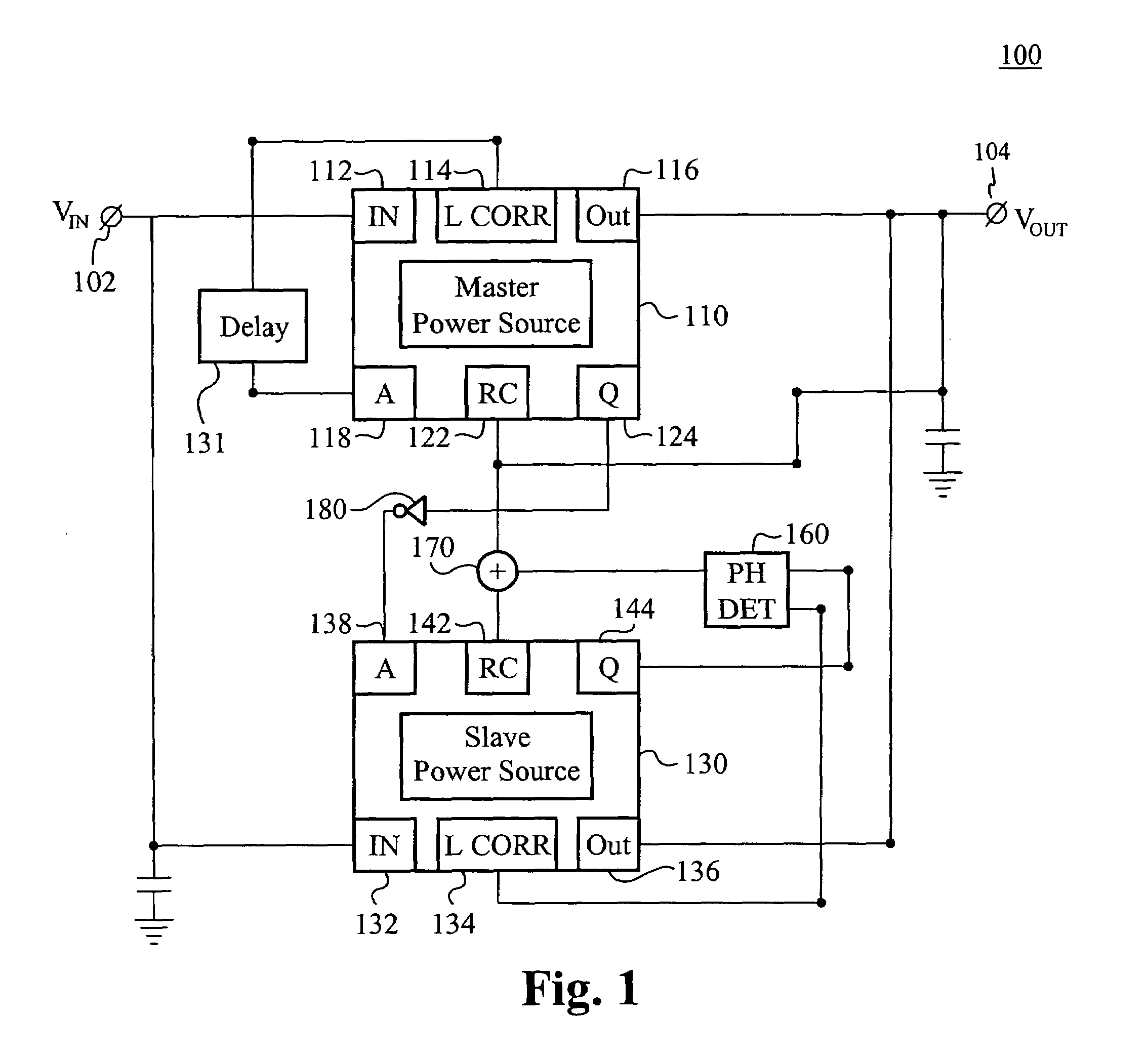
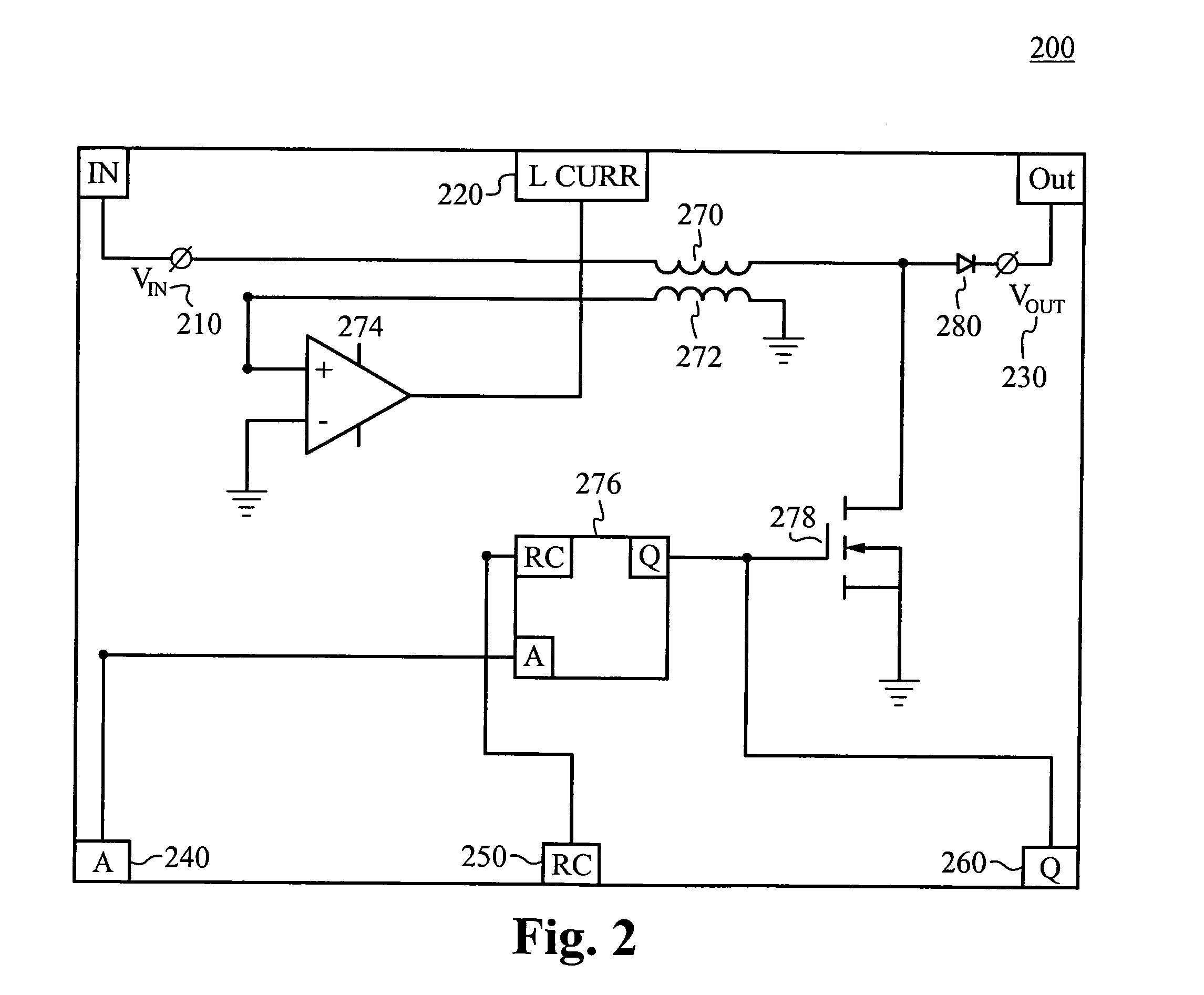
[0032]Reference will now be made in detail to the preferred and alternative embodiments of the invention, examples of which are illustrated in the accompanying drawings. While the invention will be described in conjunction with these embodiments, it will be understood that they are not intended to limit the invention to these embodiments. On the contrary, the invention is intended to cover alternatives, modifications and equivalents, which may be included within the spirit and scope of the invention as defined by the appended claims. Furthermore, in the following detailed description of the present invention, numerous specific details are set forth in order to provide a thorough understanding of the present invention. However, it should be noted that the present invention may be practiced without these specific details. In other instances, well known methods, procedures, components, and circuits have not been described in detail as not to unnecessarily obscure aspects of the present...


PUM


Abstract

A system and a method for to use multiple power sources for supplying power to a load. The system and method use a triggering system to automatically and substantially cancel a ripple component of the input current drawn by the system. A master power source and a slave power source supply power to the load. The triggering system results in the two power sources having switching frequencies that are substantially equal and switching cycles that are substantially 180° out of phase. Further, the method and the device contemplate the use of a local oscillator in the triggering system to ensure that the slave power source is triggered to the on position at a point in the switching cycle of the master power source that is approximately 180° out of phase with a leading edge of the master switching drive signal. The system and method are advantageously used to provide a power factor correction front-end for a switch-mode power supply. Power supplies with a diverse array of relationships between power supplied and switching frequency can be used.

Description

RELATED APPLICATIONS[0001]This application claims priority under 35 U.S.C. § 119(e) of the now abandoned, U.S. provisional application Ser. No. 60 / 609,508 filed on Sep. 7, 2004 and entitled “MASTER SLAVE CRITICAL CONDUCTION MODE POWER CONVERTOR,” which is hereby incorporated by reference in its entirety.FIELD OF THE INVENTION[0002]The present invention relates generally to systems for supplying power to a load and, in particular, to such systems that use plural power sources to create high output, homogenous power.BACKGROUND OF THE ART[0003]Several issues arise in the construction of power converters. The most problematic of these is the difficulty of creating noise-free output power without introducing noise into the input power. Conventional techniques directed toward this problem are well known, but complicated and expensive to implement. Conventional power converters introduce periodically varying components of the input current and can cause power loss. In addition, prior art p...

Claims


Application Information

Patent Timeline
Patent Type & Authority Patents(United States)
IPC IPC(8): G05F1/40
CPCH02J1/102H02M1/4225H02M3/1584Y02B70/126Y02B70/10
Inventor JANSEN, ARIAN
Owner MYPAQ HLDG LTD
Why Eureka
Try Eureka