Weft knitting machine with movable yarn guide member

a weft knitting machine and guide member technology, applied in weft knitting, knitting, textiles and papermaking, etc., can solve the problem that the stitch presser interferes with the yarn guide member, and achieve the effect of adjusting the density of the kni

Inactive Publication Date: 2007-04-24
SHIMA SEIKI MFG LTD
View PDF10 Cites 20 Cited by
  • Summary
  • Abstract
  • Description
  • Claims
  • Application Information

AI Technical Summary

Benefits of technology

[0012]A weft knitting machine having a movable yarn guide member of the present invention is configured such that a stitch cam for setting a density of a knit by drawing in a knitting needle holding the yarn fed from the yarn feeder is provided in the carriage in a manner so as to be able to adjust the density of the knit. The stitch cam and the yarn guide member are connected by a linking device in a manner such that when the stitch cam moves to a knit-forming side for forming the knit, the movable yarn guide member moves in a direction to advance to a side of a gap portion between the mouth portions, and when the stitch cam moves to a stitch-cam-intermitting side, or a value of the density of the knit is zero, where the knit is not formed, the movable yarn guide member moves in a direction to be retreated from the gap portion between the mouth portions to a needle bed side.
[0012]A weft knitting machine having a movable yarn guide member of the present invention is configured such that a stitch cam for setting a density of a knit by drawing in a knitting needle holding the yarn fed from the yarn feeder is provided in the carriage in a manner so as to be able to adjust the density of the knit. The stitch cam and the yarn guide member are connected by a linking device in a manner such that when the stitch cam moves to a knit-forming side for forming the knit, the movable yarn guide member moves in a direction to advance to a side of a gap portion between the mouth portions, and when the stitch cam moves to a stitch-cam-intermitting side, or a value of the density of the knit is zero, where the knit is not formed, the movable yarn guide member moves in a direction to be retreated from the gap portion between the mouth portions to a needle bed side.

Problems solved by technology

However, since the space of the mouth portion where the yarn guide member is provided is narrow, there has been a possibility that a stitch presser interferes with the yarn guide member when the stitch presser is advanced to the gap portion between the mouth portions to press a stitch, for example.

Method used


Image

  • Weft knitting machine with movable yarn guide member
  • Weft knitting machine with movable yarn guide member
  • Weft knitting machine with movable yarn guide member

Examples


first embodiment

[0021]Hereinbelow, a weft knitting machine having a movable yarn guide member with respect to a first embodiment of the present invention will be explained while referring to the drawings.

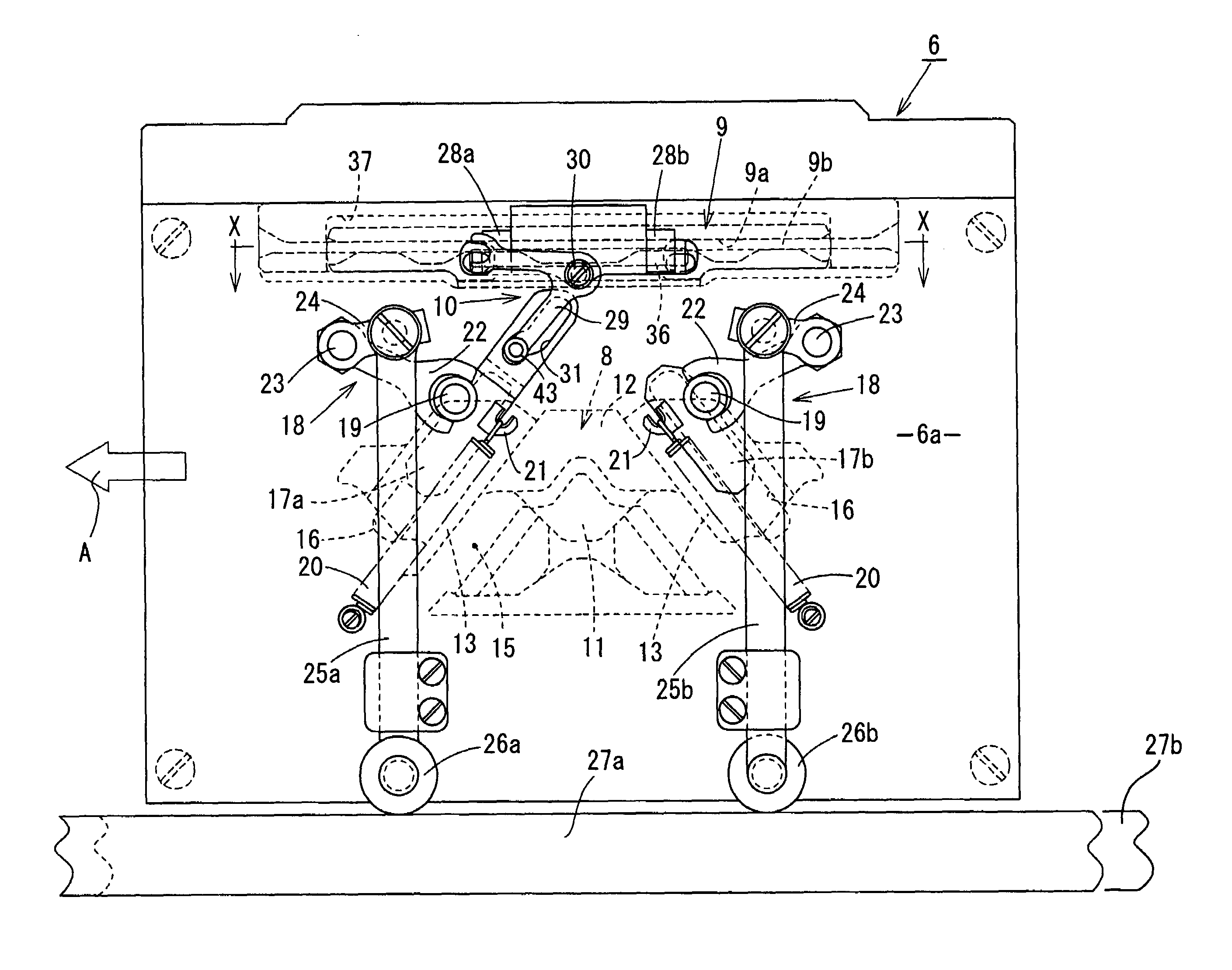
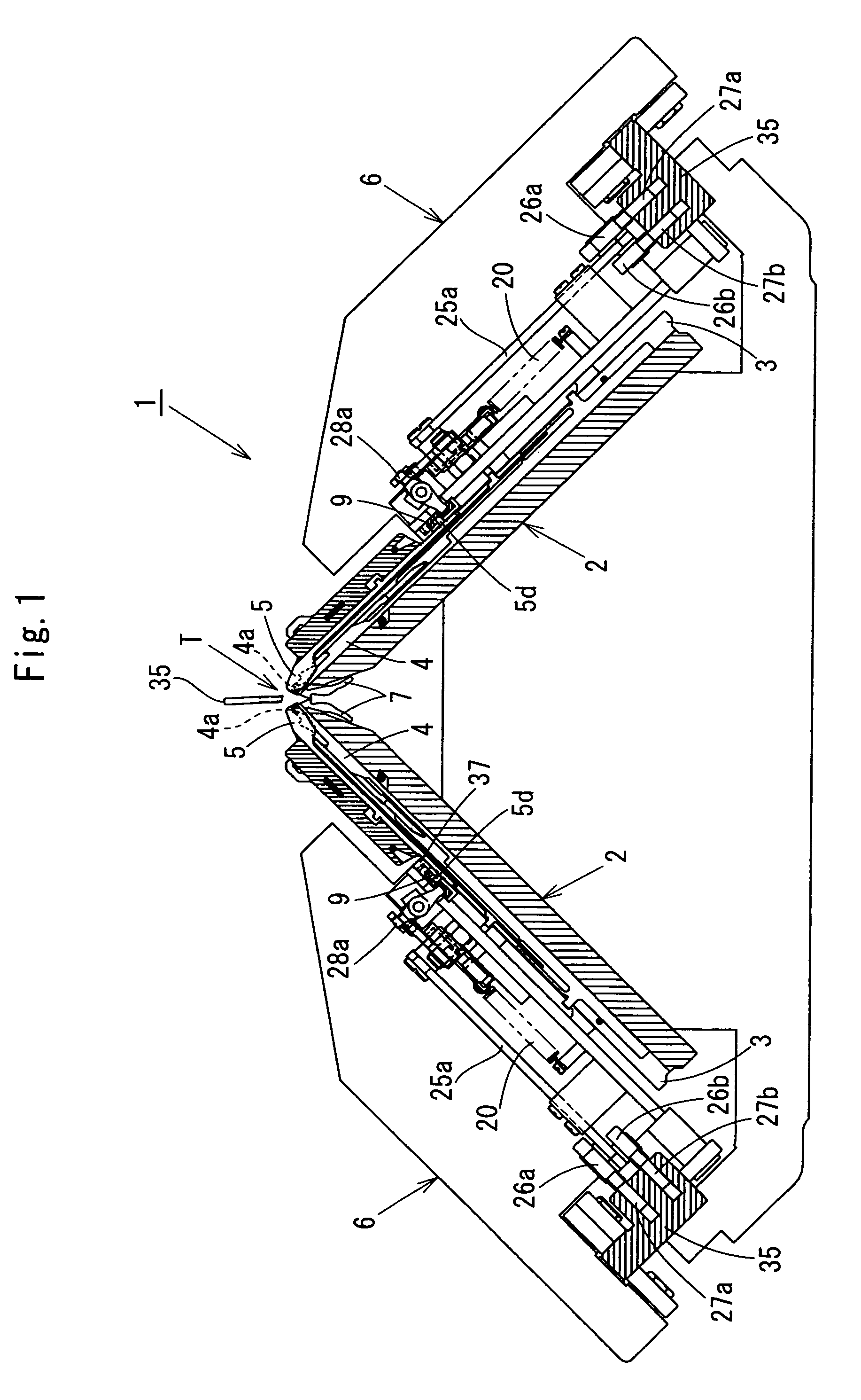
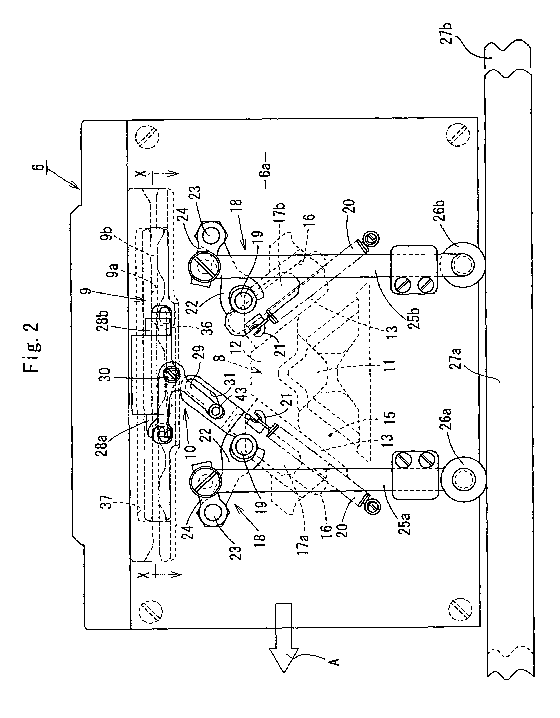
[0022]FIG. 1 is a side elevation showing a schematic construction of a mouth portion of the weft knitting machine. Number 1, in FIG. 1, denotes an entire structure of the weft knitting machine. The weft knitting machine 1 is provided with a carriage 6, shown in FIG. 2, at an upper part of the needle bed 2. Needle plates 3 are disposed on the needle bed 2 at even intervals.

[0023]A plurality of knitting needles 4 of a compound needle-type and yarn guide members 5 are respectively disposed side by side between the needle plates, 3 and 3, in a manner so as to be able to operate for advancing and retreating. A pair of the needle beds 2 is configured so that the needle beds face each other in a manner such that the mouth portion of each of the knitting needles 4 comes close together in an upside-down-V l...


PUM


Abstract

A stitch cam for setting the density of a knit by drawing in a knitting needle holding yarn fed from a yarn feeder is adjustably provided on a carriage. The stitch cam and the yarn guide member are connected by a linking device such that when the stitch cam moves to a knit-forming side, the movable yarn guide member moves in a direction to advance to a side of a gap portion between the mouth portions, and when the stitch cam moves to a stitch-cam-intermitting side, the movable yarn guide member moves in a direction to be retreated from the gap portion between the mouth portions to a needle bed side.

Description

TECHNICAL FIELD[0001]The present invention relates to a weft knitting machine having a yarn guide member, and more specifically to a weft knitting machine having a movable yarn guide member whose advancing and retreating operation for the yarn guide member is enabled.BACKGROUND ART[0002]A weft knitting machine provided with a yarn guide member for guiding yarn to a predetermined lower position so that the yarn fed from a yarn feeder is securely hooked by a knitting needle advanced to a gap portion between mouth portions by a knitting cam of a carriage is known. In the weft knitting machine, needle beds are disposed in a backward-and-forward direction in a state of confronting the mouth portion.[0003]However, since the space of the mouth portion where the yarn guide member is provided is narrow, there has been a possibility that a stitch presser interferes with the yarn guide member when the stitch presser is advanced to the gap portion between the mouth portions to press a stitch, f...

Claims


Application Information

Patent Timeline
Patent Type & Authority Patents(United States)
IPC IPC(8): D04B15/36D04B15/56D04B15/06
CPCD04B15/06D04B15/36D04B15/00
Inventor MIYAMOTO, MASAKI
Owner SHIMA SEIKI MFG LTD
Why Eureka
Try Eureka