Pressure valve
- Summary
- Abstract
- Description
- Claims
- Application Information
AI Technical Summary
Benefits of technology
Problems solved by technology
Method used
Image
Examples
Embodiment Construction
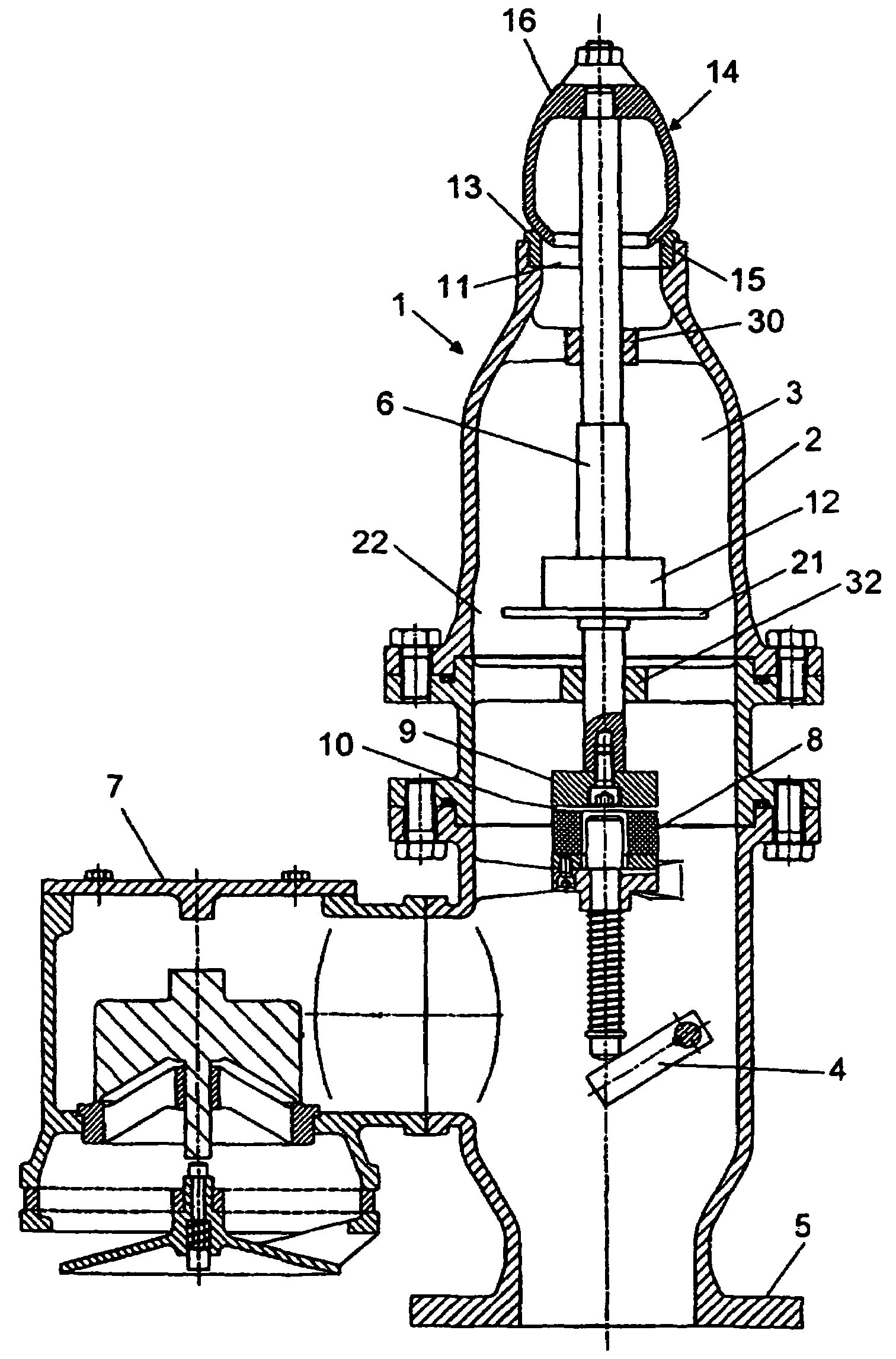
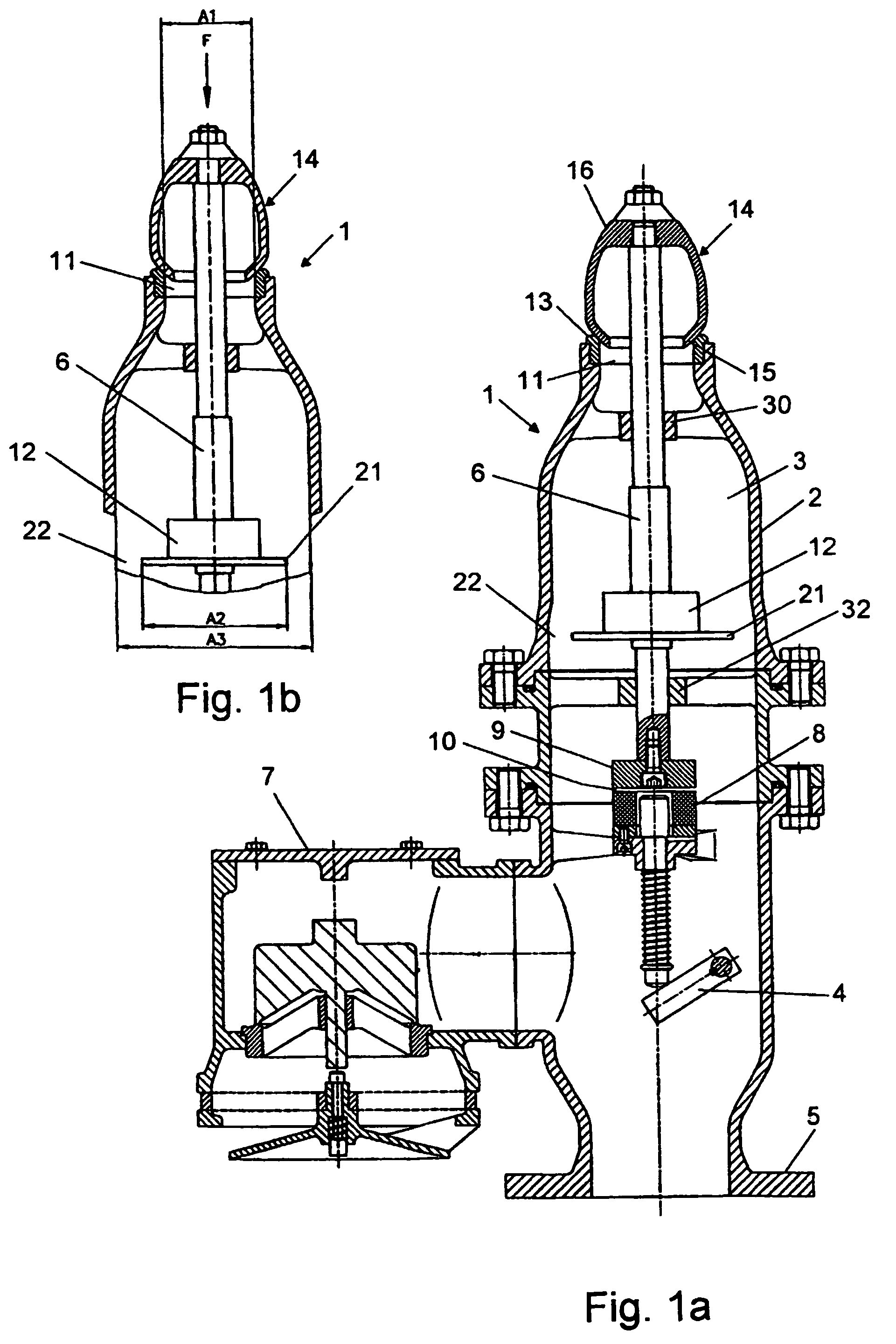
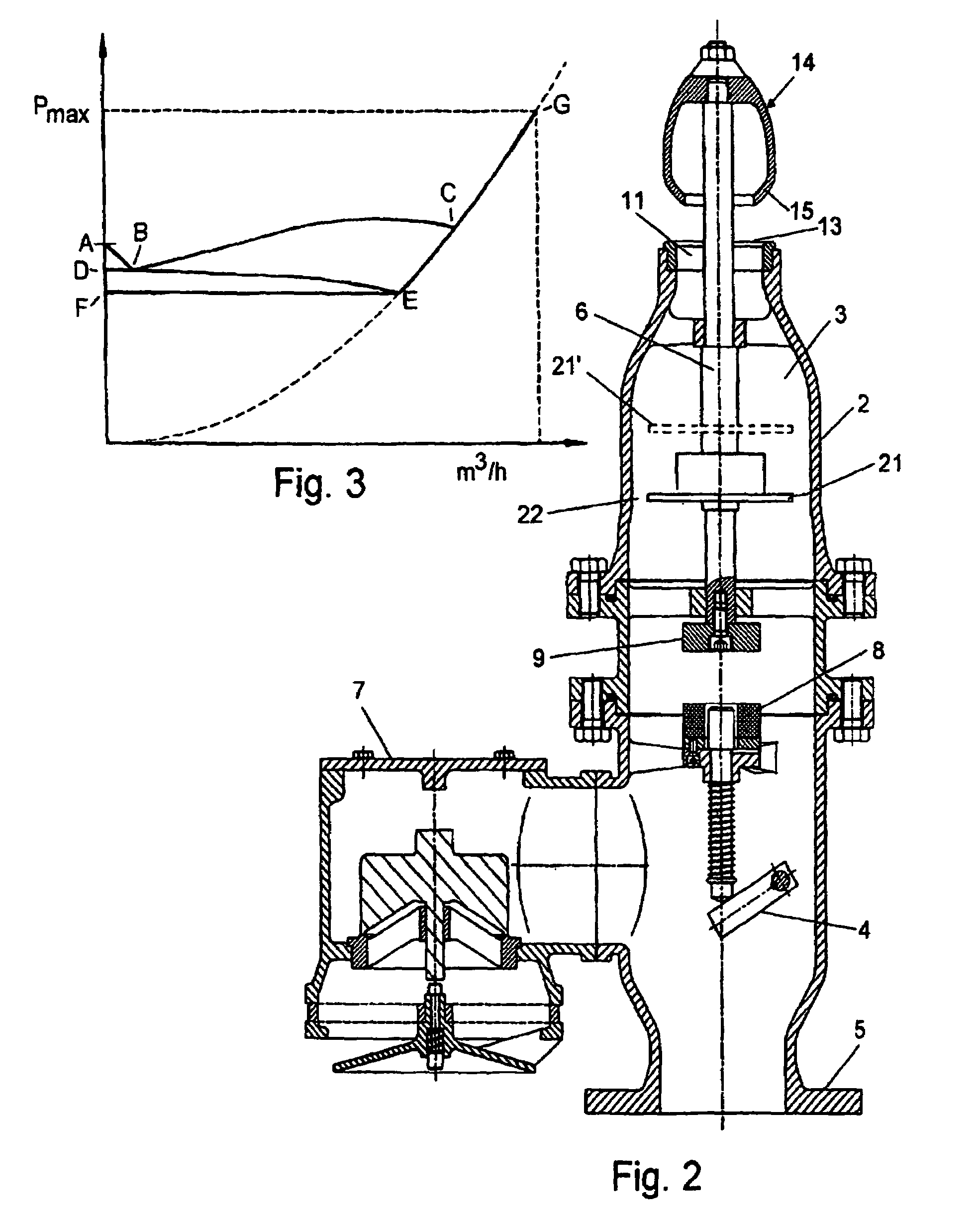
[0016]In FIG. 1a the reference numeral 1 is used to show a vertically oriented valve housing having, at the bottom, a flange 5, by which the valve housing 1 can be bolted to a pressure release stub on a gas-filled container, eg a tank or a cargo hold on a ship, or to the top end of a pressure relief tube that is connected to one or more such containers.
[0017]The pressure valve 1 has a tubular wall 2 that defines a through-going flow passage 3 with a outflow mouthing 11, whereby gas in the subjacent container may escape to the free atmosphere under particular pressure conditions. The flow passage 3 preferably has a circular cross section, but other cross-sectional configurations may be selected, including eg a rectangular cross-section. If desired a lateral opening can be provided in the tubular wall 2, to which a vacuum relief valve 7 is connected that does not constitute a part of the invention.
[0018]In the outflow mouthing 11, an annular valve seat 13 is mounted that is configured...
PUM
 Abstract
Description
Claims
Application Information
 - R&D
- Intellectual Property
- Life Sciences
- Materials
- Tech Scout
- Unparalleled Data Quality
- Higher Quality Content
- 60% Fewer Hallucinations
Browse by: Latest US Patents, China's latest patents, Technical Efficacy Thesaurus, Application Domain, Technology Topic, Popular Technical Reports.
© 2025 PatSnap. All rights reserved.Legal|Privacy policy|Modern Slavery Act Transparency Statement|Sitemap|About US| Contact US: help@patsnap.com


