Modular pressure control and drilling waste management apparatus for subterranean borehole operations

a technology of waste management equipment and subterranean boreholes, which is applied in the direction of quary waste water treatment, borehole/well accessories, multi-stage water/sewage treatment, etc., can solve the problems of vertical fracture, reduced available space and time, and time required to position and assemble pressure control and drilling waste management equipment often requires days and available space to rig up

Active Publication Date: 2007-04-24
MI
View PDF11 Cites 52 Cited by
  • Summary
  • Abstract
  • Description
  • Claims
  • Application Information

AI Technical Summary

Problems solved by technology

In addition, coiled tubing operations are used in reentering wells and drilling underbalanced.
Specially engineered fluids are pumped into the portion of the reservoir to be treated at a high pressure and rate, causing a vertical fracture to open.
Further, the decrease in available space and time has accentuated the need for decreasing the footprint and preparation time for pressure control equipment and drilling waste management equipment as well as other associated equipment.
Using conventional drilling methods, the time required to position and assemble pressure control and drilling waste management equipment often requires days and available space to rig up.

Method used


Image

  • Modular pressure control and drilling waste management apparatus for subterranean borehole operations
  • Modular pressure control and drilling waste management apparatus for subterranean borehole operations
  • Modular pressure control and drilling waste management apparatus for subterranean borehole operations

Examples


Embodiment Construction

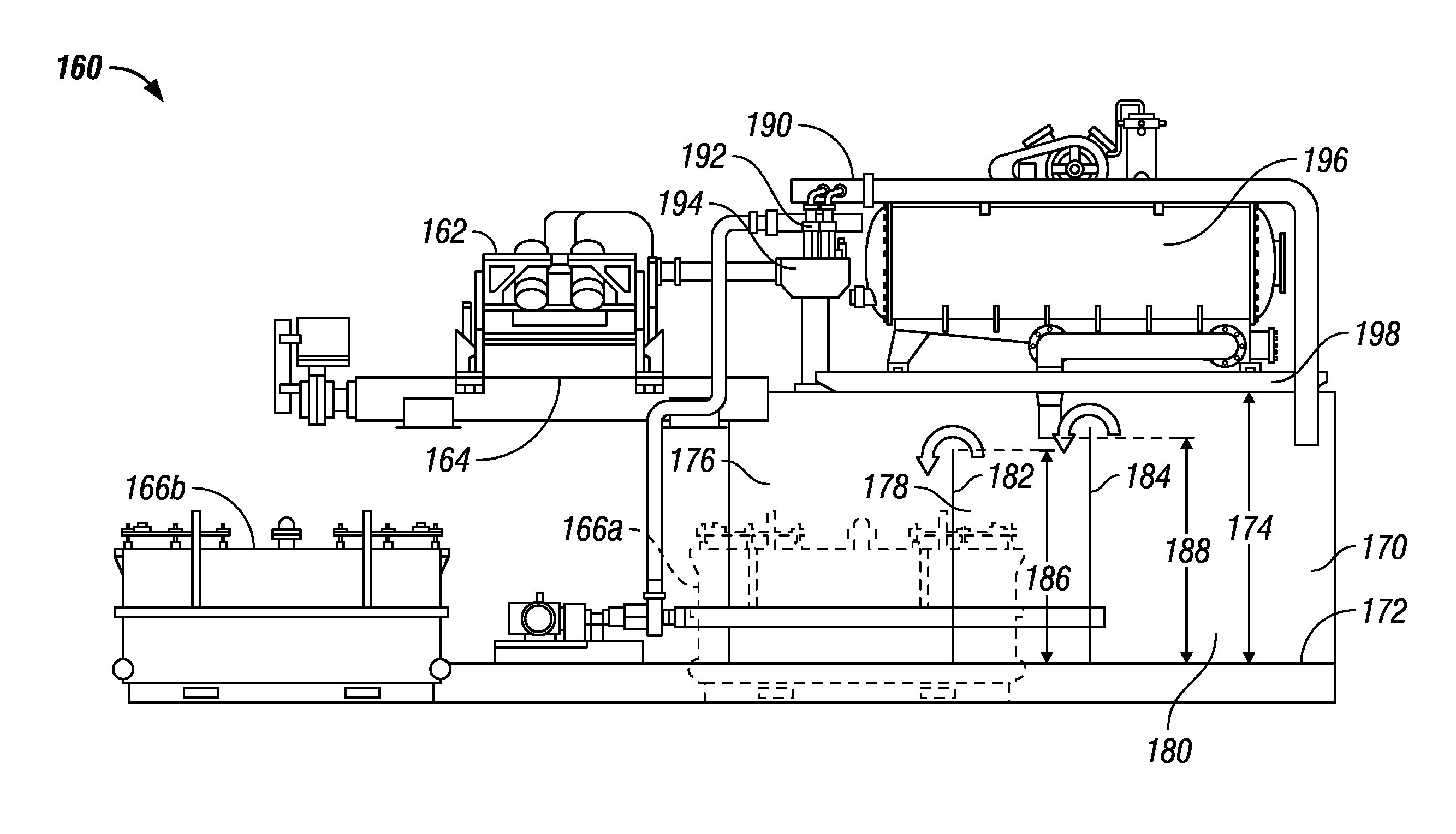
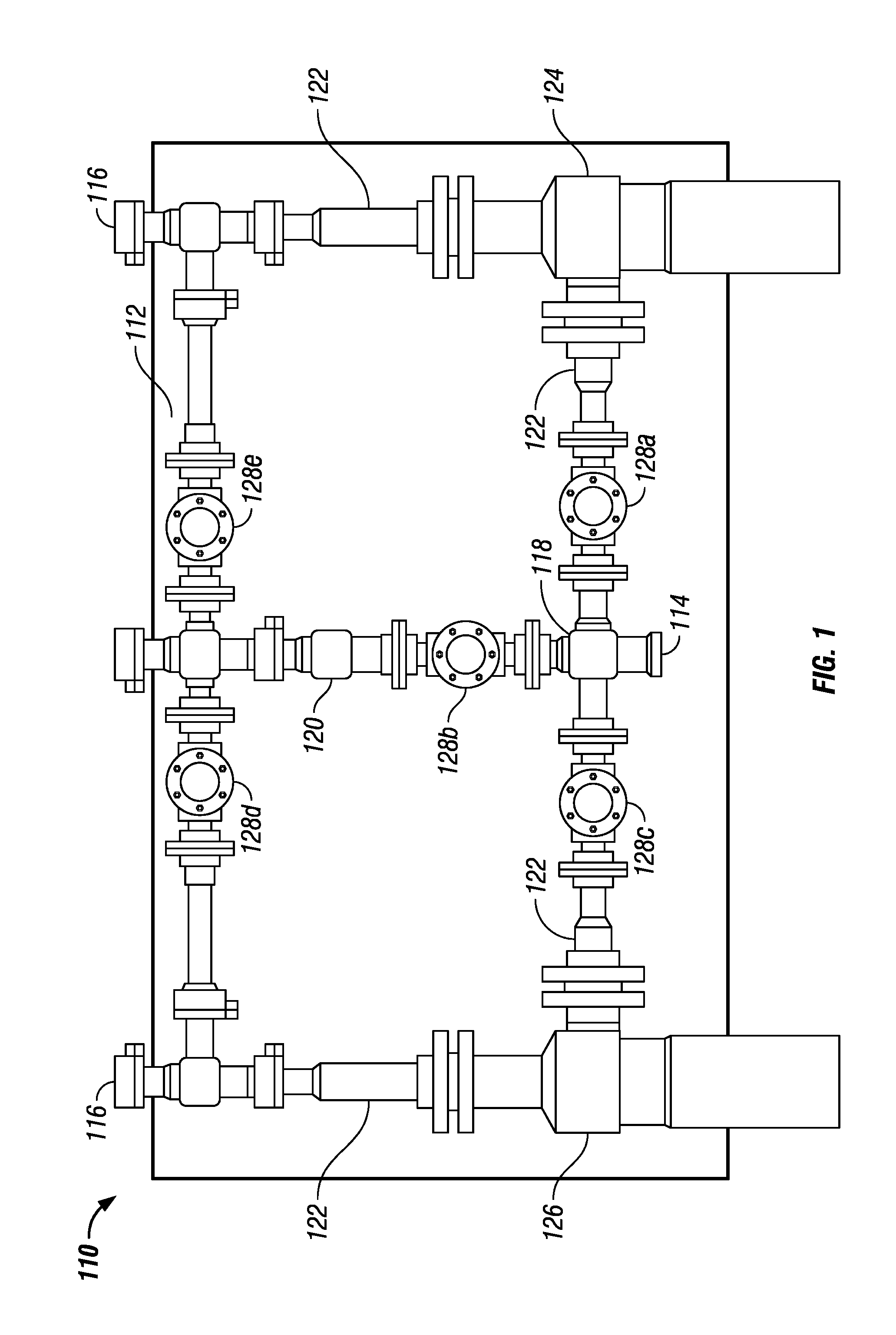
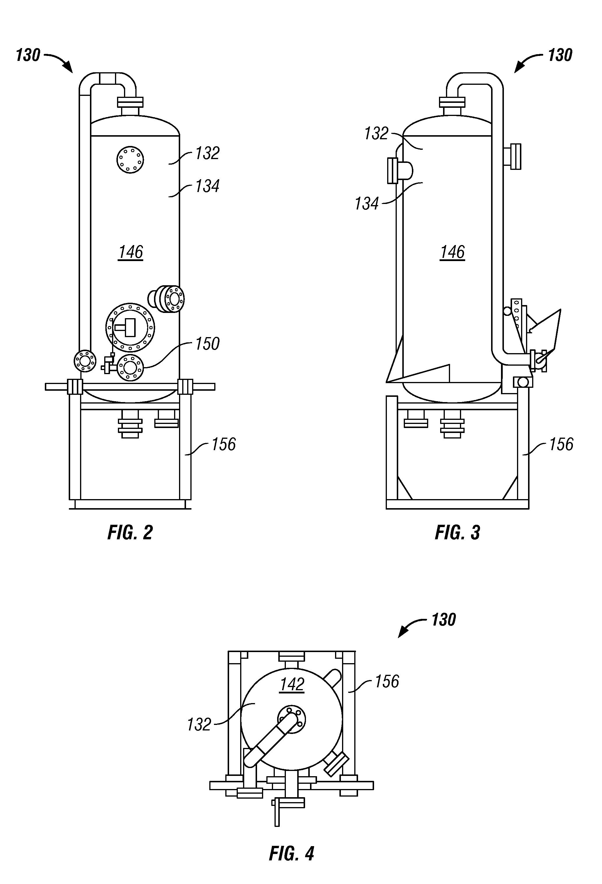
[0024]The claimed subject matter relates to a modular apparatus 100 for removing contaminants from a borehole fluid and a method for installing the apparatus. It will be appreciated by those of skill in the art that borehole fluids include drilling fluids, completion fluids, fracturing fluids, as well as other fluids that are circulated within subterranean boreholes during the various stages of drilling, completing, and maintaining a producing wellbore. As used herein, the term “subterranean borehole” includes boreholes in drilling, completion, and production operations. The apparatus includes three components, a pressure control section 110, a gas separator section 130, and a waste management section 160.

[0025]Referring to FIG. 1, the pressure control section 110 includes a pressure control manifold 118 interconnecting at least two chokes 124, 126. The chokes 124, 126 used in the pressure control section 110 are preferably automatic chokes, providing accurate pressure control.

[0026...


PUM

PropertyMeasurementUnit
pressureaaaaaaaaaa
pressureaaaaaaaaaa
heightaaaaaaaaaa

Abstract

A modularly segmented apparatus for precise borehole pressure control, removing waste from borehole fluid, and recirculating the cleaned borehole fluid includes a pressure control section, a gas separator section, and a waste management section. In the pressure control section, a pressure manifold interconnects a plurality of chokes. A plurality of valves are used to direct the contaminated fluid through one of the chokes, which maintains a precise and predetermined pressure in the system. The manifold, chokes, and valves are mounted on a skid for easy transport. In the gas separator section, a gas separator is used to remove a majority of the gases present in the contaminated borehole fluid. In the waste management section, a vibratory separator removes large solid contaminants from the degassed fluid. The solids are directed to a solids collection container for further treatment or disposal. The fluid is directed to a first pit, which may be one partitioned are of a larger collection tank. Fluid from the first pit is directed to a degasser which removes additional gases in the fluid and directs the fluid to a second pit. Fluid from the second pit is directed to a desilter, which removes additional solids and directs the fluid to a third pit. The solids from the desilter are directed to the solids collection container. Fluid from the third pit is directed to active rig pumps for recirculation into the borehole.

Description

[0001]This application claims the benefit of U.S. Provisional Application No. 60 / 615,715 filed Oct. 4, 2004 and U.S. Provisional Application No. 60 / 615,730 filed Oct. 4, 2004, the contents of which are incorporated herein by reference.BACKGROUND OF INVENTION[0002]The rigs used to drill many oil and / or gas wells currently enjoy much smaller footprints than oil and / or gas wells of the past. Technology, such as coiled tubing operations, has led to a decrease in the space required to perform drilling and / or completion operations on oil or gas wells and a decrease in the time required to prepare for and to perform such operations.[0003]Coiled tubing operations includes coiled tubing drilling, where downhole mud motors turn the bit to deepen a borehole. Coiled tubing drilling is useful in applications such as drilling slimmer wells and for areas where a small rig footprint is essential. In addition, coiled tubing operations are used in reentering wells and drilling underbalanced.[0004]In ...

Claims


Application Information

Patent Timeline
Patent Type & Authority Patents(United States)
IPC IPC(8): E21B21/06
CPCC02F1/20C02F1/34E21B21/066E21B21/106C02F9/00C02F2103/10
Inventor DUHE, JASONGHARST, JAMESSIMON, LEGAL REPRESENTATIVE, STELLADELAHOUSSAYE, PAULSIMON, DECEASED, KELVIN
Owner MI
Why Eureka
Try Eureka