Boom stand

Active Publication Date: 2007-04-24
ROBERTS JEFFREY A +2
View PDF48 Cites 24 Cited by
  • Summary
  • Abstract
  • Description
  • Claims
  • Application Information

AI Technical Summary

Benefits of technology

[0018]A first object of the invention is to provide a movable and yet densely stored support stand. A second object of the invention is to ensure rigid orientation of boom to stand even under substantial forces, while still providing the benefits of elastomeric coupling and isolation. Another object of the present invention is to obtain the foregoing objects using mechanisms which are intuitive to operate and which may be operated quickly. An additional object of the inve

Problems solved by technology

Unfortunately, in the prior art this often led to the use of a large and very massive base, typically of disc, slightly domed, or similar shape.
Such a base is not readily transported, nor can it be used or stored in close arrangement with other bases.
Consequently, it is not possible to tightly and compactly arrange, use or store a plurality of similar stands.
These stands are extremely undesirable for several different reasons.
Long legs in turn form a serious hazard for anyone passing near to the boom stand.
In the event a boom stand is accidentally knocked over, the item supported thereon may be destroyed.
In the case of the performing arts, the microphones that are supported thereon may cost thousands of dollars to replace.
Furthermore, the disruption to a performance when a stand is accidentally toppled is highly undesirable.
As is known in the industry

Method used


Image

  • Boom stand
  • Boom stand
  • Boom stand

Examples


Embodiment Construction

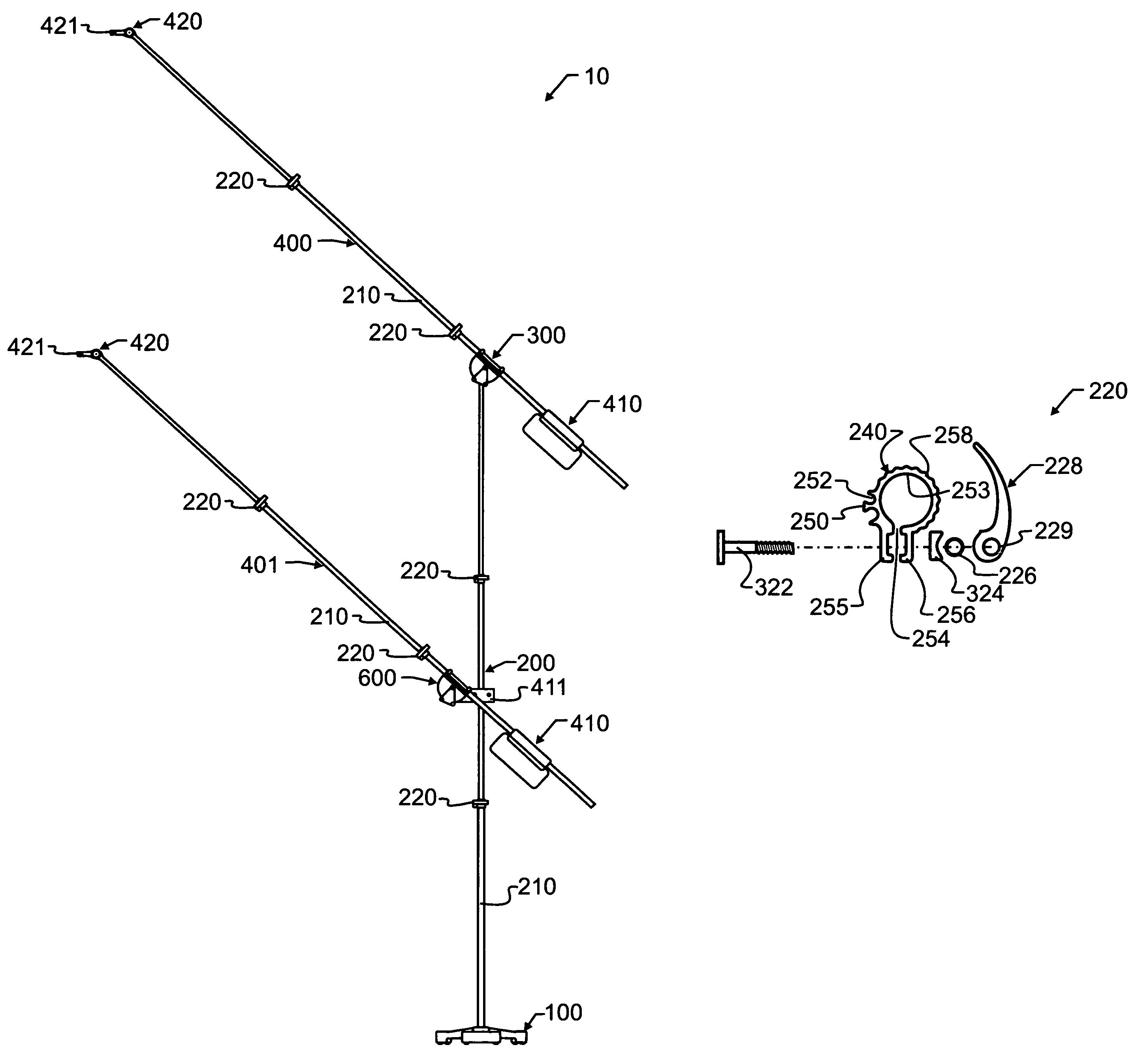
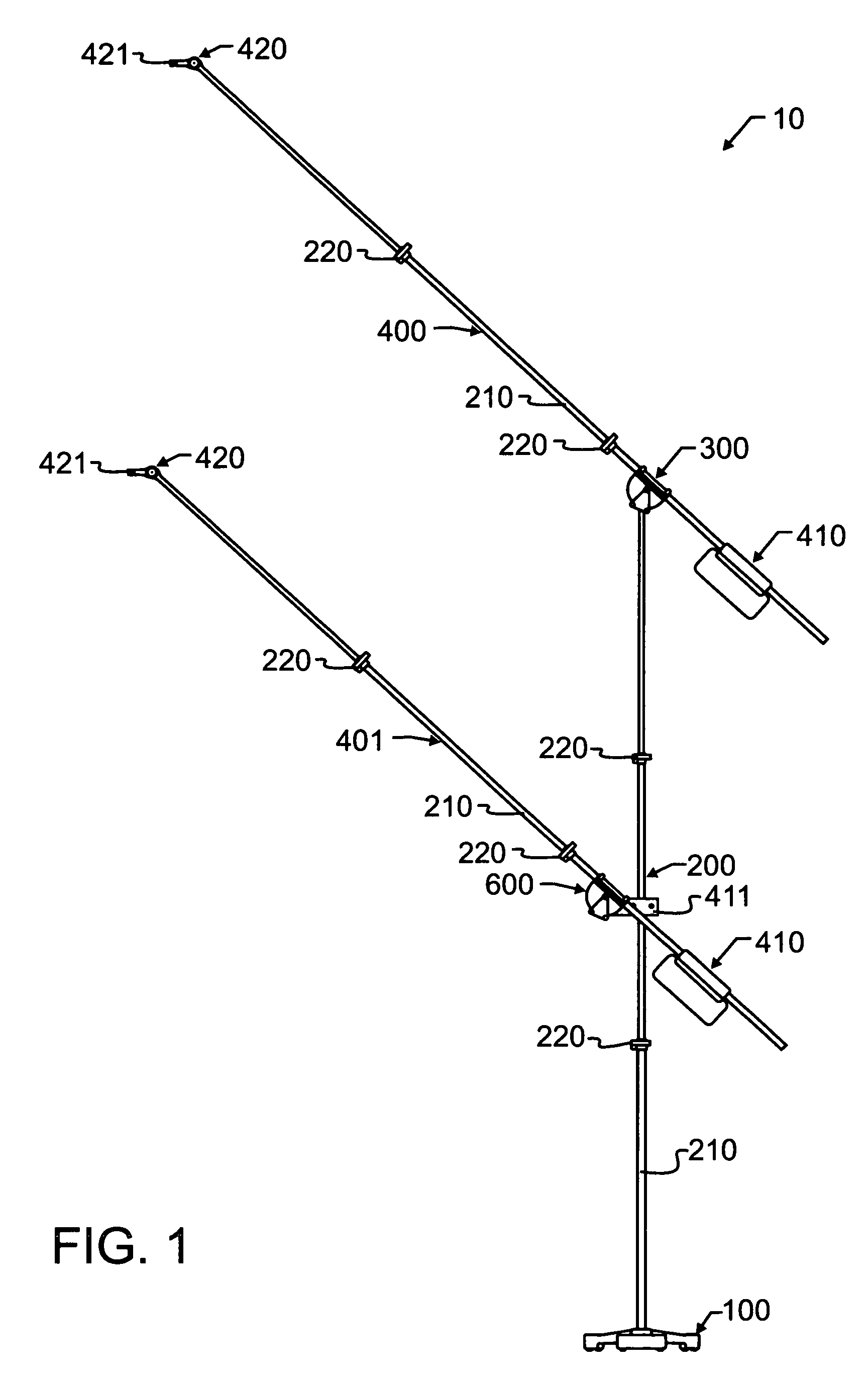
[0040]Manifested in the preferred embodiment, the present invention provides a boom stand 10 which is adapted to support one or more of a variety of known devices thereon. More specifically, but not limited thereto, microphones, cameras, lights, medical equipment, and many other devices may be supported therefrom. For reasons to be explained herein below, the support of sensitive electrical or electronic equipment is most preferred, especially pertaining to microphones, but the application of the present invention is not solely limited thereto and is instead contemplated by the present inventors to have other applications as well.

[0041]Boom stand 10 includes a base 100 which is designed to support boom stand 10 upon a floor or other surface. Most preferably, though not an absolute requisite, the floor or other surface will be relatively planar or flat, at least in the region adjacent to base 100. This permits base 100 to be formed with points of contact all in a planar relationship,...


PUM


Abstract

A boom stand is constructed from a base, extensible stand, pivotal boom support, and boom. The base has arcuately segmented massive anchors that form a perimeter. The arcuately segmented massive anchors are shaped and sized to fit within the perimeter of like bases, to decrease minimum distances between stands during storage or close use, while still providing stability. Over-center clamps provided on the extensible stand are extruded to include unitary cord guides, and are engaged with tube ends to prevent rotation or accidental removal. The pivotal boom support incorporates a disc and elastomeric pads to provide superior locking and vibration reduction, and utilizes in alternative embodiments perimeter and central over-center clamps which further enhance the operation.

Description

BACKGROUND OF THE INVENTION[0001]1. Field of the Invention[0002]This invention pertains generally to supports, and more specifically to stands, brackets and bases for supports. In a most preferred manifestation of the invention, the invention pertains to microphone stands.[0003]2. Description of the Related Art[0004]Boom stands, which will be understood herein as vertically rising stands having at least one arm capable of extension in a horizontal direction, are used to support many diverse items. Lights, microphones, cameras, and many other electrical and non-electrical items too numerous to individually list herein are supported thereon. Most commonly, the item to be supported will preferably be easily relocated, as will the stand or at least the boom. This ability to provide relatively adjustable and easily relocated support is in great demand. Frequently, a plurality of these boom stands will be required, such as, for exemplary purposes but not limited thereto, in the case of a ...

Claims


Application Information

Patent Timeline
IPC IPC(8): F16M13/00
CPCF16C11/10F16M11/06F16M11/10F16M11/28F16M2200/022
Inventor ROBERTS, JEFFREY A.TITUS, JOHN S.JENNE, JAMES F.
Owner ROBERTS JEFFREY A
Why Eureka
Try Eureka