Latency stirring in fluid ejection mechanisms

a fluid ejection system and nozzle technology, applied in printing and other directions, can solve the problems of purged fluids that must be deposited somewhere, the nozzles of fluid ejection systems are purging, and the liquid is deposited prematurely,

Inactive Publication Date: 2007-04-24
EASTMAN KODAK CO
View PDF8 Cites 1 Cited by
  • Summary
  • Abstract
  • Description
  • Claims
  • Application Information

AI Technical Summary

Benefits of technology

[0008]According to another feature of the present invention, a method of mixing a liquid includes providing a liquid in a chamber having an orifice through which a drop of the liquid can be emitted; and creating a surface tension gradient on the liquid provided by the chamber, wherein the liquid flows without being emitted from the chamber.

Problems solved by technology

The problems associated with the premature drying of liquids such as inks, within fluid delivery devices such as inkjet printers, are known.
The premature drying of liquids causes the plugging of ejection nozzles that will either impede or totally prevent liquids from being delivered through the nozzle and onto a desired delivery medium.
A significant drawback to purging of nozzles within fluid ejection systems exists in that the purged fluids must be deposited somewhere.
However, purging receptacles such as sponges and the like have limited storage volume and become full requiring costly and often inconvenient service requirements.
Service, the replacement of sponges, and the use of cleaning cycles increases the cost of printing and adds to the complexity of printer mechanisms.
Additionally, full and saturated receptacles can contaminate the very nozzles that you are trying to clean, by virtue of cross-contaminating wet sponge material into nozzles that are already clean.
Also, in typical printing applications, the image-wise requirement of placing ink droplets upon a receiver will leave certain nozzles unused.
Asano teaches that the molecular-weight distribution of inks increases because of molecular clumping and causes erratic or clogged ink nozzles, and additionally that the practice of simple ink stirring does not sufficiently address problems such as sedimentation or cohesion, those types of problem being solved by the aggressive method of using a complicated and costly ultrasonic device.

Method used


Image

  • Latency stirring in fluid ejection mechanisms
  • Latency stirring in fluid ejection mechanisms
  • Latency stirring in fluid ejection mechanisms

Examples


Embodiment Construction

[0018]The present description will be directed in particular to elements forming part of, or cooperating more directly with, apparatus in accordance with the present invention. It is to be understood that elements not specifically shown or described may take various forms well known to those skilled in the art.

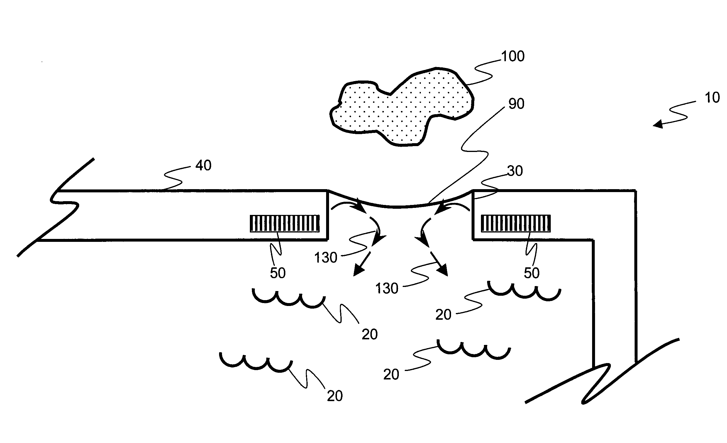
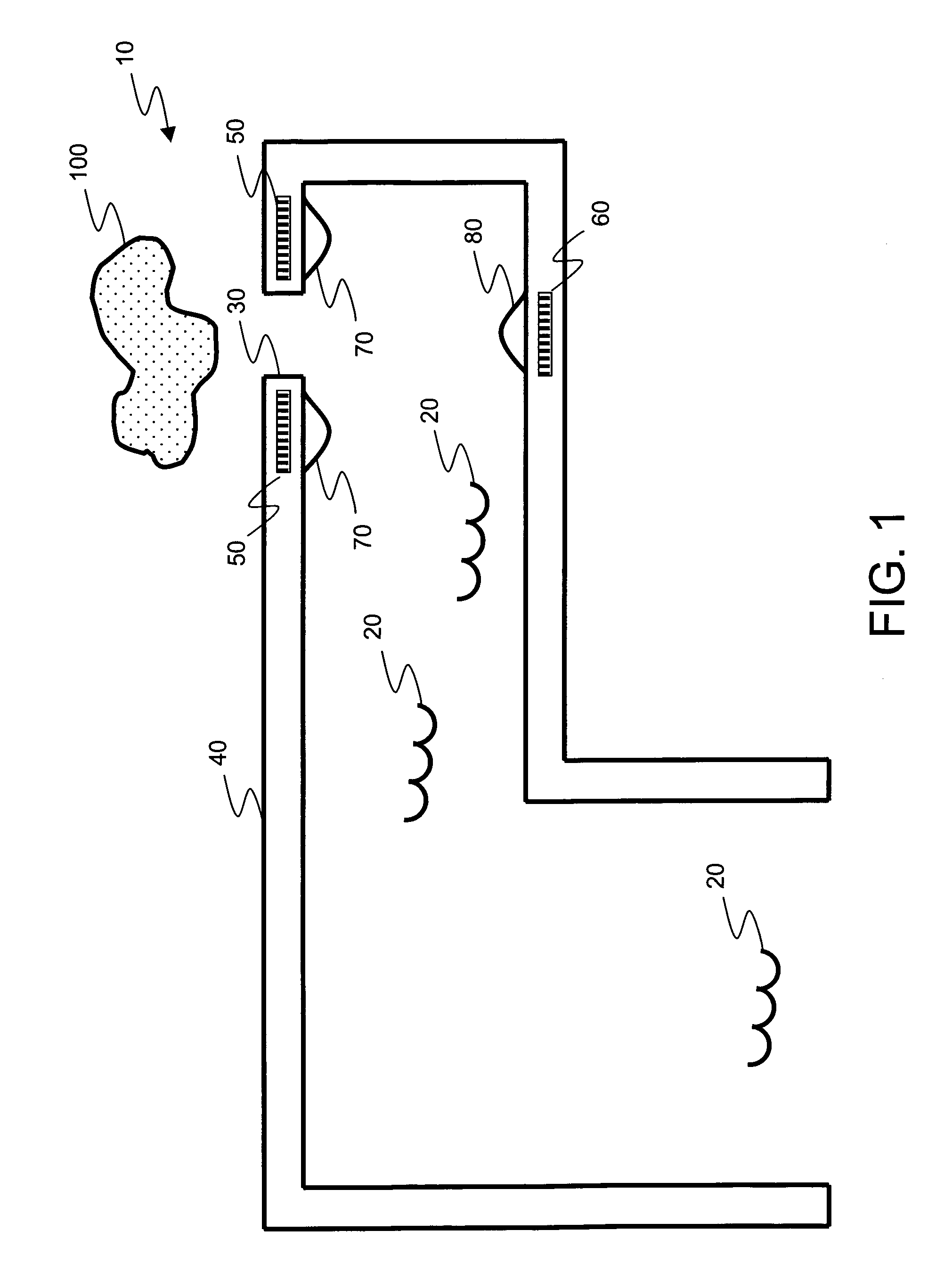
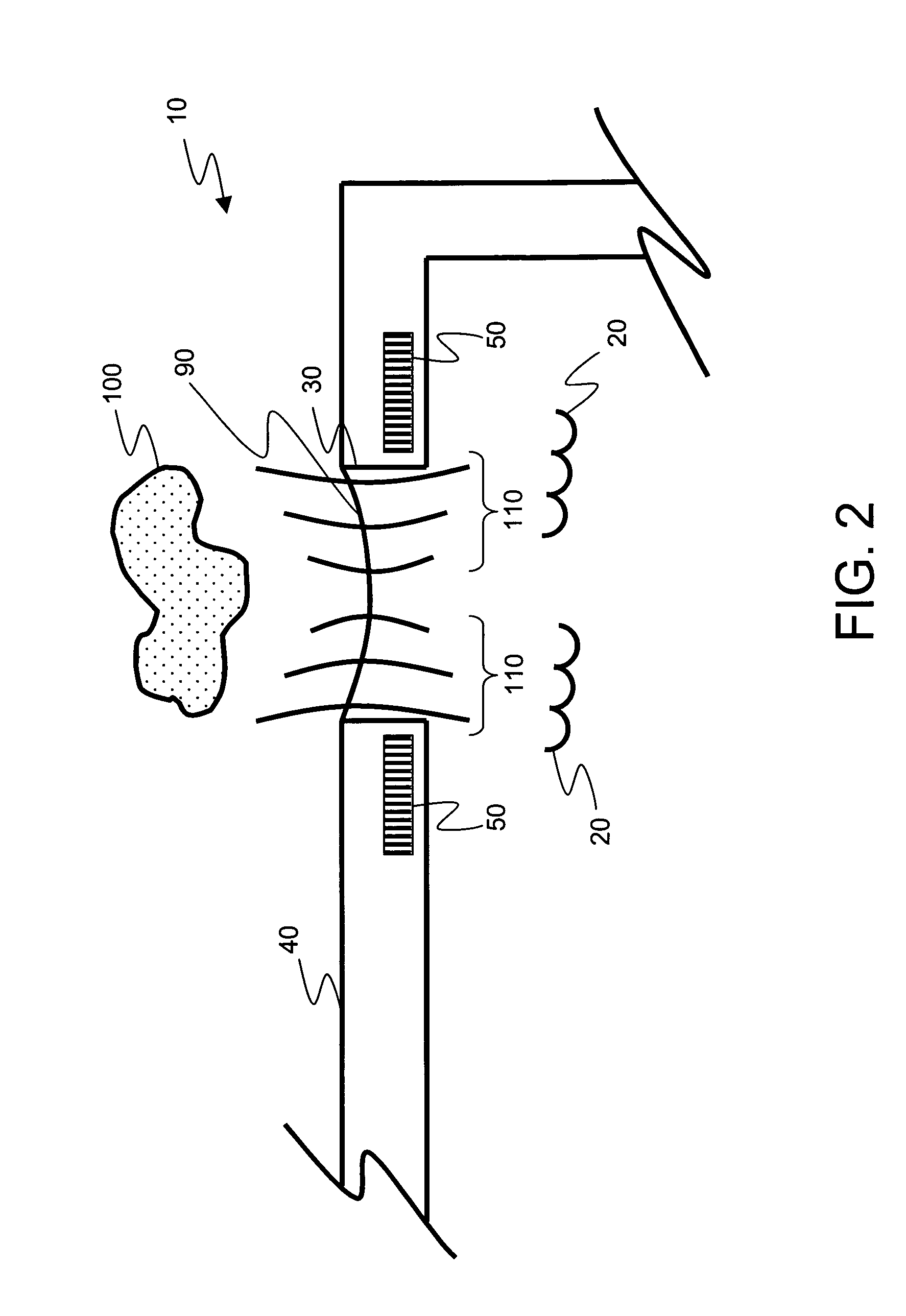
[0019]Referring to FIG. 1, the drawing illustrates a cross-sectional view of an inkjet chamber 10, for an ink jet print head that contains ink 20 to be ejected from a nozzle 30 that is disposed upon a chamber roof 40. It should be noted at this point in time that the present invention contemplates the ejection of a multiplicity of possible fluids such as medicines, inks, pigments and the like. However, for purposes of clarity and consistency, fluids will be hereafter referred to as inks. Inkjet chamber 10 also contains a plurality of heaters including upper ejection heaters 50 and lower ejection heaters 60 depending upon the type of ejection mechanism used. If upper ejection h...


PUM


Abstract

A liquid drop emitter, a method of mixing a liquid, and a method of printing are provided. The liquid emitter includes a structure defining a chamber adapted to provide a liquid having an orifice through which a drop of the liquid can be emitted. A drop forming mechanism is operatively associated with the chamber. A mixing mechanism is associated with the chamber and is operable to create a surface tension gradient on the liquid provided by the chamber such that the liquid flows without being emitted from the chamber.

Description

FIELD OF THE INVENTION[0001]The present invention relates generally to the field of inkjet printing but more specifically to the surface tension induced stirring of liquids that are to be ejected by a liquid ejection mechanism.BACKGROUND OF THE INVENTION[0002]The problems associated with the premature drying of liquids such as inks, within fluid delivery devices such as inkjet printers, are known. The premature drying of liquids causes the plugging of ejection nozzles that will either impede or totally prevent liquids from being delivered through the nozzle and onto a desired delivery medium. The plugging that occurs within liquid ejection nozzles has created a need for methods that remove such blockages, such as purging of the nozzles.[0003]Those skilled in the art of inkjet printers are aware that software exists to verify the proper operation of liquid ejection nozzles. The software also provides various routines to exercise those nozzles to purge them of dried or drying liquids....

Claims


Application Information

Patent Timeline
Patent Type & Authority Patents(United States)
IPC IPC(8): B41J2/04B41J2/165B41J2/17
CPCB41J2/165B41J2002/16502
Inventor DELAMETTER, CHRISTOPHER N.VERMA, ALOKTRAUERNICHT, DAVID P.STEPHANY, THOMAS M.
Owner EASTMAN KODAK CO
Why Eureka
Try Eureka