
Drive apparatus for tape-like optical recording medium

Inactive Publication Date: 2007-04-24
SONY CORP
View PDF7 Cites 2 Cited by
  • Summary
  • Abstract
  • Description
  • Claims
  • Application Information

AI Technical Summary

Benefits of technology

[0030]In the apparatus for driving a tape-shaped optical recording medium thus constituted in accordance with the invention claimed in any one of claims 1 to 11 of the present application, since the guide face portion for facing to the tape-shaped optical recording medium is formed with the flat portion of the running guide means for guiding the tape-shaped optical recording medium running between the reel means, a space between the tape-shaped optical recording medium and the guide face portion is stably and continuously maintained to be very small over a relatively wide area on the flat portion of the running guide means. Consequently, when a light beam obtained from a light beam controlling and signal processing portion is incident upon the tape-shaped optical recording medium running between the reel means on the flat portion of the running guide means, an area on the guide face portion where an incident position on the tape-shaped optical recording medium of the light beam obtained from the light beam controlling and signal processing portion is fixed invariably can be stably maintained to be relatively wide.

Problems solved by technology

As a result, when the light beam obtained from the light beam controlling and signal processing portion is incident upon the tape-shaped optical recording medium running between the reel means on the flat portion of the running guide means, a focus servo control for the light beam which requires an undesirable high speed control in response to the running of the tape-shaped optical recording medium can be unnecessary.

Method used


Image

  • Drive apparatus for tape-like optical recording medium
  • Drive apparatus for tape-like optical recording medium
  • Drive apparatus for tape-like optical recording medium

Examples


Embodiment Construction

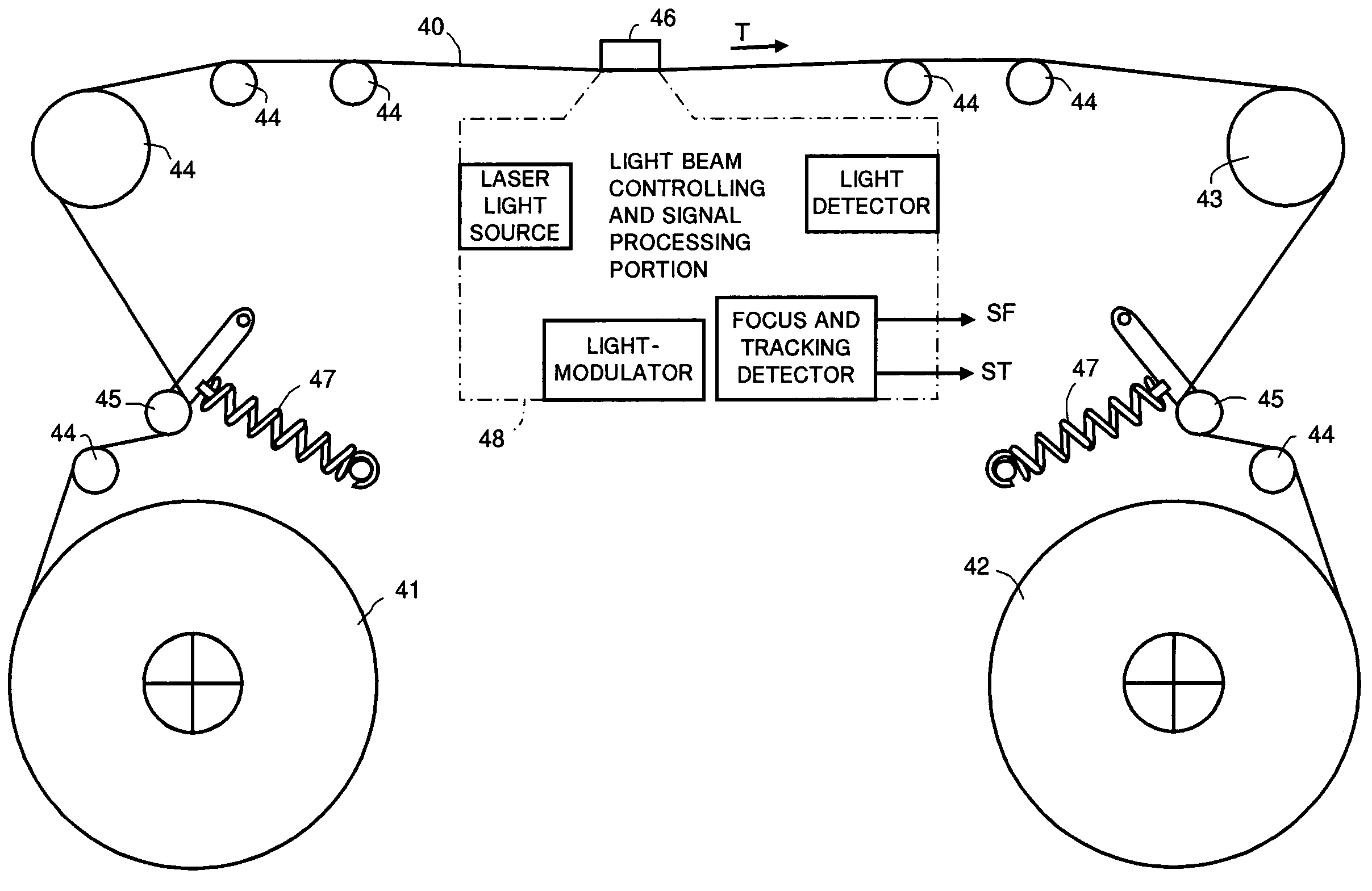
[0053]FIG. 5 shows an essential part of an embodiment of apparatus for driving a tape-shaped optical recording medium according to the invention claimed in any one of claims 1 to 11 of the present application.

[0054]In the embodiment shown in FIG. 5, a supply reel 41 on which an optical tape 40 as an optical recording medium is wound to be derived therefrom and a take-up reel 42 onto which the optical tape 40 is wound are provided. The optical tape 40 between the supply reel 41 and the take-up reel 42 is driven by a friction capstan 43 to run in the direction indicated with an arrow T (the T direction) from the supply reel 41 to the take-up reel 42.

[0055]Further, in the embodiment shown in FIG. 5, a plurality of positioning members 44, a pair of tension regulators 45 and a running guide member 46 are provided for causing the optical tape 40 driven by the friction capstan 43 to run stably though a predetermined position. The positioning members 44 determine a running path for the opti...


PUM


Abstract

An apparatus for driving a tape-shaped optical recording medium, which comprises a supply reel (41) for supplying an optical tape (40), a take-up reel (42) for taking-up the optical tape (40), a friction capstan (43) for driving the optical tape (40) to run to the take-up reel (42) from the supply reel (41) and a running guide member (46) for guiding the optical tape (40) running between the supply reel (41) and the take-up reel (42). The running guide member (46) has a flat portion forming a guide face portion (70) for facing to the optical tape (40) is operative to cause the optical tape (40) to run along the flat portion. Thereby, an area on the guide face portion (70) of the running guide member (46) where an incident position on the optical tape (40) of a light beam is fixed invariably can be stably maintained to be relatively wide.

Description

TECHNICAL FIELD[0001]The invention disclosed in each of claims of the present application relates to an apparatus for driving a tape-shaped optical recording medium on which information is recorded by a light beam incident thereupon or from which recorded information is read by a light beam incident thereupon.TECHNICAL BACKGROUND[0002]In the field of information recording on a recording medium and information reproduction from a recording medium on which the information is recorded, under the circumstances wherein recording and reproduction of data representing moving pictures performed with a relatively small-scale recording and reproducing instrument are desired, it is strongly required more than before to have arrangements for recording information on a recording medium with high data density, increasing data rate of information to be recorded on or reproduced from a recording medium and so on. Accordingly, with the intention of meeting such requirements, there has been proposed ...

Claims


Application Information

Patent Timeline
IPC IPC(8): G11B7/00G11B7/003G11B7/24009G11B15/60G11B15/64G11B15/68G11B17/22
CPCG11B7/003G11B15/607G11B15/64G11B15/6805G11B17/225
Inventor HARA, MASAAKISAWAI, JUNITO, YUJIRO
Owner SONY CORP
Learn More