Systems and methods for providing remote monitoring of electricity consumption for an electric meter

a technology of electric meters and remote monitoring, applied in the field of remote operation systems, can solve the problems of increasing the cost of developing the local sensor-actuator infrastructure necessary to interconnect the various devices, increasing the cost of connecting functional sensors and actuators with the local controller, and increasing the cost of integrating the cost of various devices. to achieve the effect of cost-effectiveness

Inactive Publication Date: 2007-04-24
LANDISGYR TECH
View PDF240 Cites 314 Cited by
  • Summary
  • Abstract
  • Description
  • Claims
  • Application Information

AI Technical Summary

Problems solved by technology

One problem with expanding the use of automated monitoring system technology to distributed systems is the cost associated with developing the local sensor-actuator infrastructure necessary to interconnect the various devices.
Not only is there expense associated with developing and installing appropriate sensors and actuators, but the added expense of connecting functional sensors and actuators with the local controller is also problematic.
Another prohibitive cost is the expense associated with the installation and operational expense associated with programming the local controller.
Another problem with expanding the use of automated monitoring system technology is the cost of the sensor / actuator infrastructure required to monitor and control such systems.
Another prohibitive cost of such is the installation and operational expenses associated to the local controller.
Furthermore, it is difficult to use existing automated monitoring systems to monitor electricity consumption.
Currently, a residential homeowner and / or a commercial user cannot easily and inexpensively determine their electricity consumption remotely.
Currently available systems have prohibitive costs as well as complicated installation and maintenance requirements.

Method used


Image

  • Systems and methods for providing remote monitoring of electricity consumption for an electric meter
  • Systems and methods for providing remote monitoring of electricity consumption for an electric meter
  • Systems and methods for providing remote monitoring of electricity consumption for an electric meter

Examples


Embodiment Construction

[0022]Having summarized the invention above, reference is now made in detail to the description of the invention as illustrated in the drawings.

[0023]While the invention will be described in connection with these drawings, there is no intent to limit it to the embodiment or embodiments disclosed therein. On the contrary, the intent is to cover all alternatives, modifications and equivalents included within the spirit and scope of the invention as defined by the appended claims.

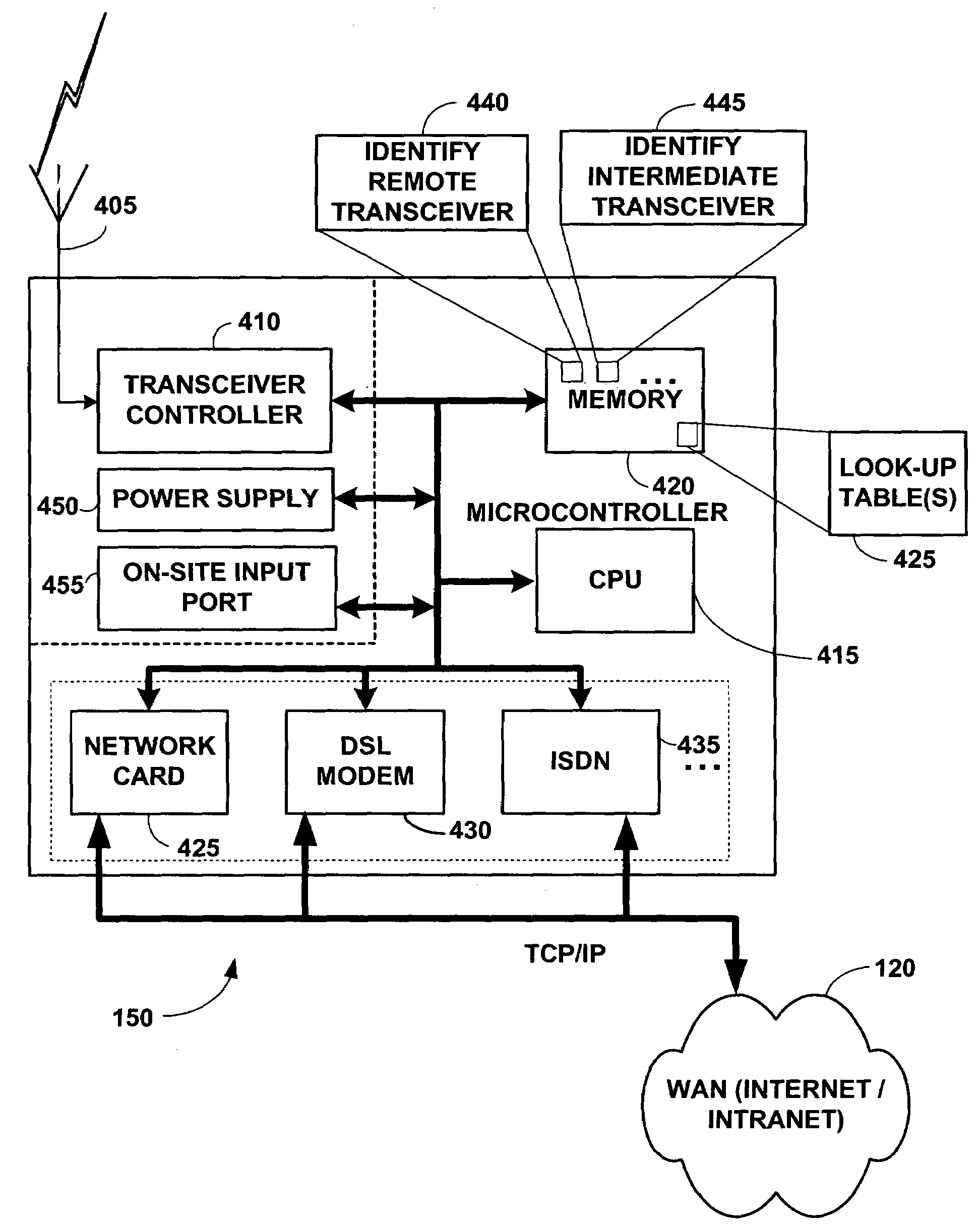
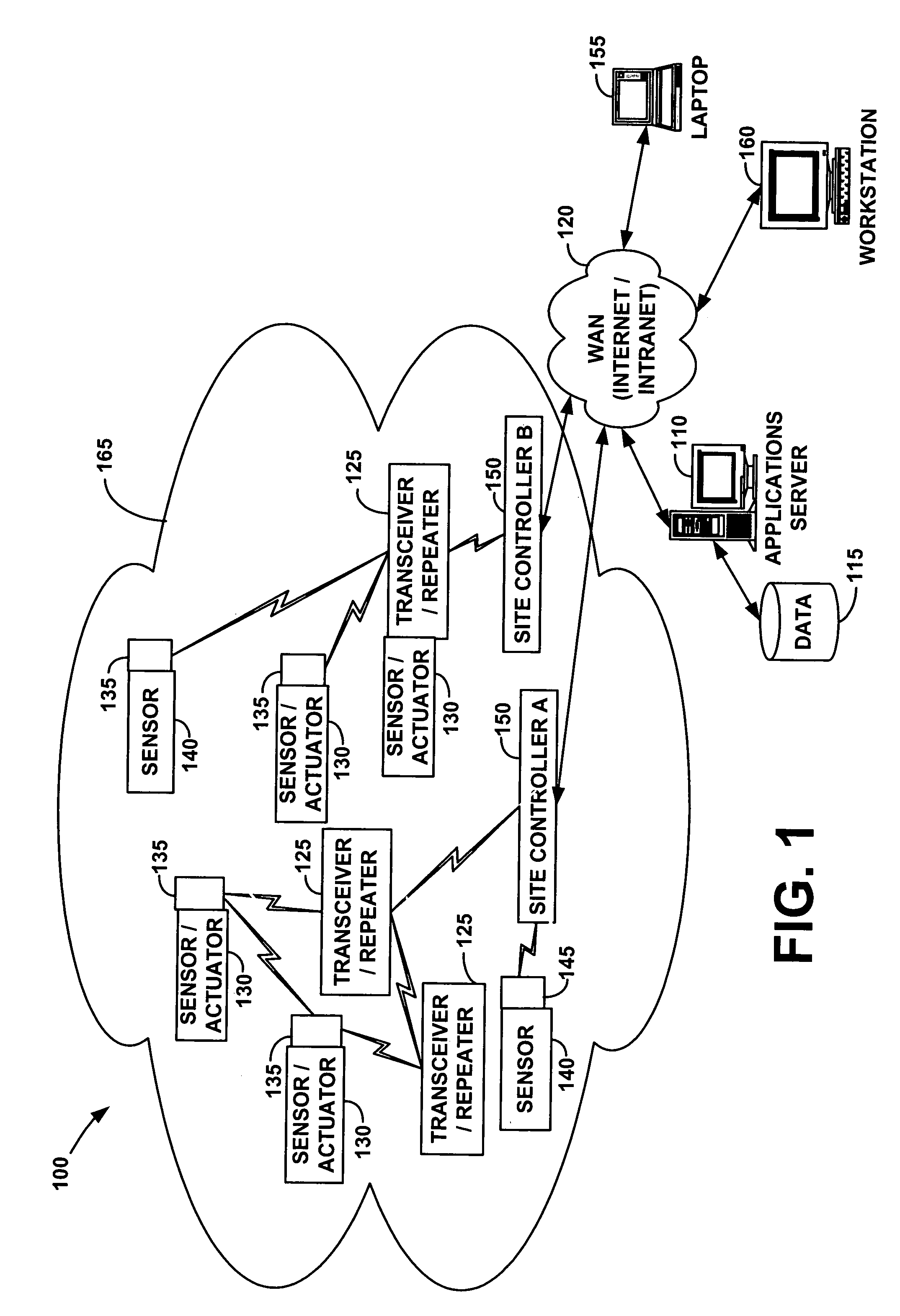
[0024]FIG. 1 sets forth a block diagram that illustrates one of a number of embodiments of an automated monitoring system 100 according to the present invention. Automated monitoring system 100 may comprise an applications server 110, one or more site controllers 150, and a series of remote devices, such as sensors 140 and sensors / actuators 130. The applications server 110 may communicate with a user via a laptop 155, workstation 160, etc. One or more site controllers 150 and the applications server 110 may co...


PUM


Abstract

A system for providing remote monitoring of electricity consumption is provided. In one embodiment the system may comprise electric meters, communication devices having a unique address and defining a wireless communication network, and a site controller. Each electric meter may be configured to measure electricity consumption of a load. Each communication device may be associated with one of the electric meters and configured to receive electricity consumption data and generate a transmit message using a predefined communication protocol being implemented by the wireless communication network. The transmit message may comprise the unique identifier and electricity consumption data. The site controller may be configured for communication with the wireless communication network and configured to receive the transmit message from one of the communication devices, identify the electric meter associated with the transmit message, and provide information related to the transmit message to a WAN for delivery to a computer.

Description

CROSS-REFERENCE TO RELATED APPLICATION[0001]This application is a continuation of U.S. patent application Ser. No. 0 / 925,393, filed Aug. 9, 2001, entitled “Systems and Methods for Providing Remote Electricity Consumption for an Electric Meter,” which has issued as U.S. Pat. No. 6,836,737 and which is hereby incorporated by reference in its entirety. U.S. patent application Ser. No. 09 / 925,393 was a continuation-in-part of U.S. patent application Ser. No. 09 / 704,150, which was filed on Nov. 9, 2000 and has issued as U.S. Pat. No. 6,891,838. Also, U.S. patent application Ser. No. 09 / 925,393 claimed the benefit of provisional application No. 60 / 224,065, filed Aug. 9, 2000.FIELD OF THE INVENTION[0002]The present invention generally relates to remotely operated systems, and more particularly to systems and methods for providing remote monitoring of electricity consumption for an electric meter.BACKGROUND[0003]There are a variety of systems for monitoring and / or controlling any of a numbe...

Claims


Application Information

Patent Timeline
Patent Type & Authority Patents(United States)
IPC IPC(8): G08C17/00G01D4/00G01R22/00G08C17/02H02J13/00H04B17/00H04L12/26H04L12/56H04Q9/00
CPCG01D4/004G08C17/02H02J13/0075H04L12/2602H04L43/00H04Q9/00G01R22/00G08C2201/40G08C2201/42G08C2201/51H04L43/10H04W8/205Y02B90/242Y04S20/322Y04S40/168Y02B70/3241Y02B90/245Y02B90/246Y04S20/227Y04S20/40Y04S20/42Y04S10/30Y02E60/74H04Q2209/40H04Q2209/60H02J13/00002H02J13/00017Y02B90/20Y02E60/00Y04S20/30Y04S40/00H02J13/00022Y02B70/30Y04S20/20
Inventor PETITE, THOMAS D.HUFF, RICHARD M.
Owner LANDISGYR TECH
Why Eureka
Try Eureka