Active tester for vehicle circuit evaluation

a technology of active tester and vehicle circuit, which is applied in the direction of testing circuits, material electrochemical variables, instruments, etc., can solve the problems of voltage drop, resistance or impedance of the cable connecting the starter and the battery is too high, cumbersome tasks,

Inactive Publication Date: 2007-04-24
SNAP ON INC
View PDF6 Cites 70 Cited by
  • Summary
  • Abstract
  • Description
  • Claims
  • Application Information

AI Technical Summary

Benefits of technology

[0014]A beneficial aspect of a tester according to this disclosure is provided by using an included signal source for conducting the test. A test result can be obtained even if the circuit under test is not in operation. A further beneficial aspect of a tester according to this disclosure is the ability of the tester to provide test results for different test parameters without the need to actually conduct multiple tests using different test parameters.

Problems solved by technology

This can be a cumbersome task, sometimes requiring an additional technician to monitor the voltage display while the other technician cranks the vehicle at the same time.
For example, a possible cause to the abnormal voltage drop may be that the resistance or impedance of a cable connecting the starter and battery is too high.
Rust and corrosion are common problems with the terminal connections of the cable which add unwanted resistance to this circuit.
For example, a possible cause to the abnormal voltage drop may be that the resistance or impedance of a cable connecting the alternator and battery is too high.
A shortcoming of the conventional approach is that the multiple steps for measuring the voltage drop and work involved to measure the cable resistance add complexity to the testing procedure and it can be time consuming, thus adding additional expense to the repair cost.
However, the circuit under test is not always in working condition or in operation.
As a result, the test cannot be performed.
However, it is not always possible to generate or duplicate the required testing parameters as required by the specification.
Even if it is possible, it is burdensome to perform multiple tests using various test parameters.

Method used


Image

  • Active tester for vehicle circuit evaluation
  • Active tester for vehicle circuit evaluation
  • Active tester for vehicle circuit evaluation

Examples


Embodiment Construction

[0021]In the following description, for the purposes of explanation, numerous specific details are set forth in order to provide a thorough understanding of the present disclosure. It will be apparent, however, to one skilled in the art that the present method and system may be practiced without these specific details. In other instances, well-known structures and devices are shown in block diagram form in order to avoid unnecessarily obscuring the present disclosure. For illustration purpose, the following examples describe the operation of an exemplary tester used for evaluating a circuit of an automotive vehicle. It is understood that the use of tester is not limited to vehicle circuits. The tester also can be used in other types of electrical circuits.

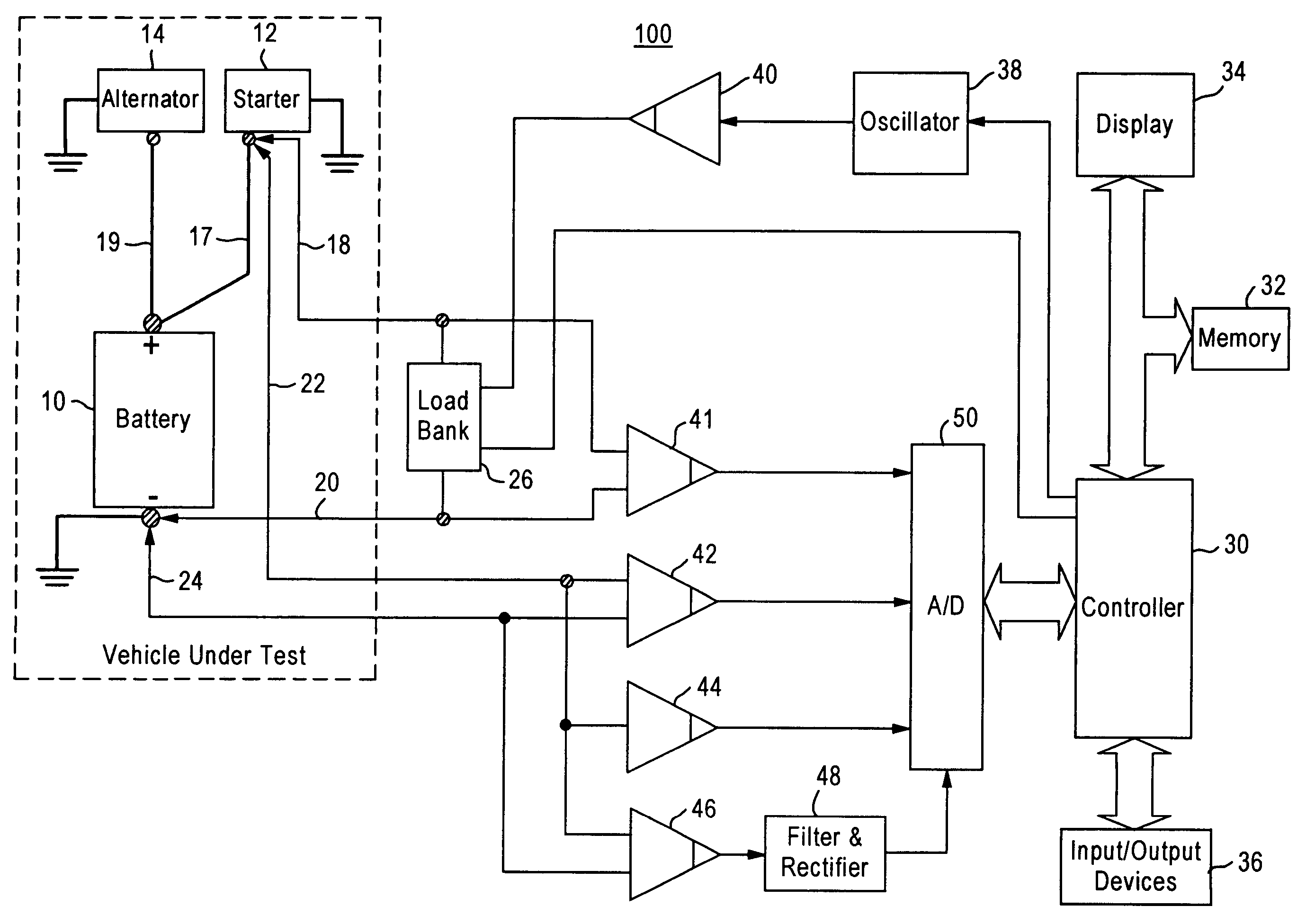
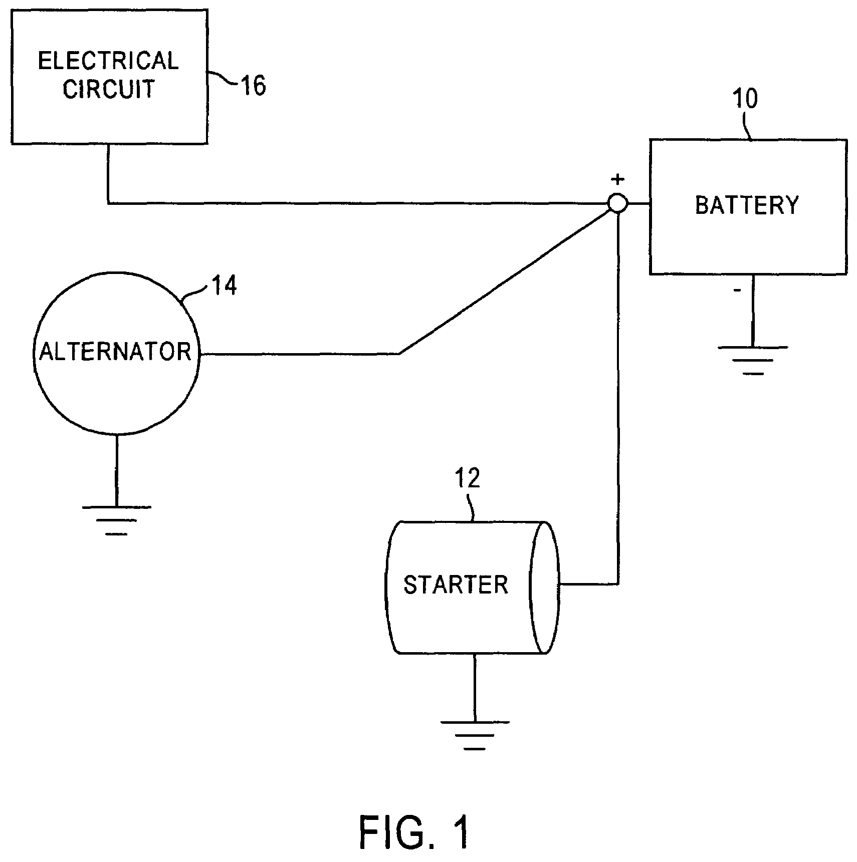
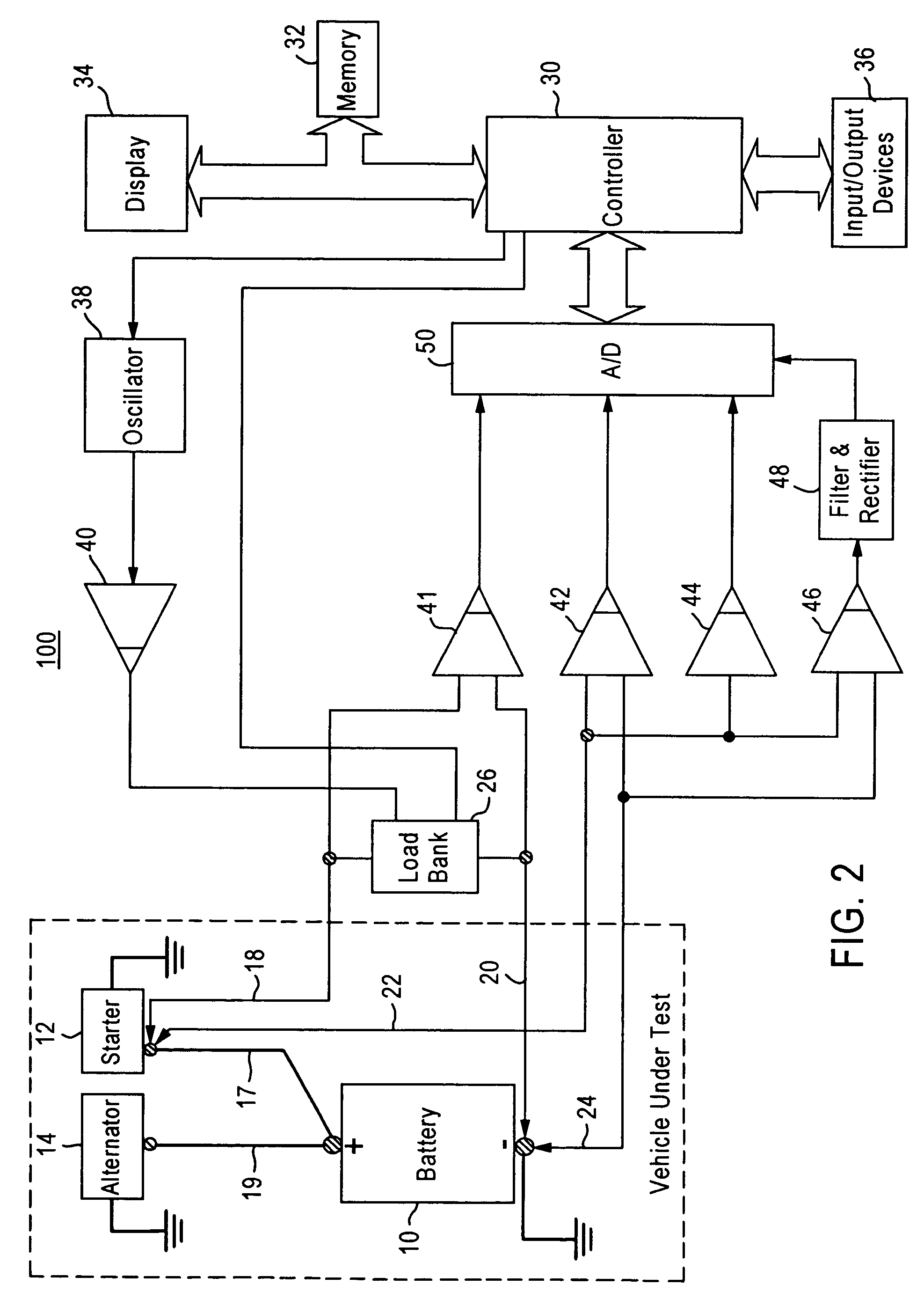
[0022]FIG. 1 is a generalized block diagram of a vehicle electrical system. Battery 10, starter 12 and alternator 14 are shown connected in parallel for simplicity of illustration. An auxiliary test terminal also may be provided to...


PUM


Abstract

An active tester for vehicle circuit evaluation includes a signal source for generating a dynamic signal, such as an AC current, for injecting to a circuit under test. The tester includes a data storage device for storing at least one test parameter and a data processor for processing data. In operation, the data processor controls to apply the dynamic signal to the separated points of the circuit via the first set of terminals. The response of the circuit under test to the applied dynamic signal is measured. The data processor determines a dynamic parameter of the circuit under test as a function of the dynamic signal and the response. The data process then generates a test result related to the characteristics of the circuit as a function of the at least one test parameter and the determined dynamic parameter. The test result is compared with specification values to determine whether the circuit under test works normally.

Description

RELATED APPLICATIONS[0001]This application relates to copending U.S. patent application Ser. No. 10 / 619,187, filed Jul. 15, 2003 and titled TESTING AND DISPLAY OF ELECTRICAL SYSTEM IMPEDANCE, the disclosure of which is incorporated herein by reference in its entirety.TECHNICAL FIELD[0002]The present disclosure relates to circuit testing, and more particularly, to an active method and system for determining the health of a vehicle circuit, even when no current or voltage has been established by the operation of the circuit.BACKGROUND[0003]In the automotive industry, it has been a known practice to evaluate the health of starting and / or charging circuit components by measuring a voltage drop corresponding to a specific input current between two separate points of the circuit, and comparing the measurement with specification values. For instance, for determining the health of a starting circuit (which may include a starter, a battery, a solenoid, cables and terminals) in an automotive ...

Claims


Application Information

Patent Timeline
Patent Type & Authority Patents(United States)
IPC IPC(8): G01R27/28G01R31/00G01R31/14G06F19/00
CPCG01R31/006
Inventor BROTT, ALEJANDRO P.THIBEDEAU, DENNIS
Owner SNAP ON INC
Why Eureka
Try Eureka