
System, apparatus and method for controlling temperature of an integrated circuit under test

a technology of integrated circuit and temperature control, applied in the direction of electrical testing, measurement devices, instruments, etc., can solve the problems of non-functional testers detecting chip failures, using failures, and likely failing at a higher frequency rate than is acceptabl

Inactive Publication Date: 2006-07-13
GOOGLE LLC
View PDF10 Cites 22 Cited by
  • Summary
  • Abstract
  • Description
  • Claims
  • Application Information

AI Technical Summary

Benefits of technology

The patent describes a system, method, and apparatus for controlling the temperature of an integrated circuit during testing. The system includes a cold plate that is connected to a source of chilled fluid and a heater for supplying heat to the cold plate. The system also includes a thermal control system that can adjust the flow rate of the chilled fluid or the power supplied to the heater to control the temperature of the integrated circuit. The technical effects of this system include improved accuracy and control over the temperature of the integrated circuit during testing, as well as improved reliability and repeatability in testing results.

Problems solved by technology

Chip testers such as functional or non-functional testers may detect chip failures during testing at different operating temperatures.
Some early use failures which might not have normally occurred until after reaching a customer may be found during testing at elevated temperatures.
Such a part may pass tests and reach a customer, but will likely fail at a higher frequency rate than is acceptable.
Failure to precisely control thermal conditions during chip testing may result in finding fewer faults, having to increase the guardband on sorted speed, and reduced ability to determine power dissipation.
These failures may result in lower chip yields, lower customer satisfaction, higher warranty costs, and overall decrease in efficiency in chip production.
These problems are exacerbated as chips become more and more powerful, as more powerful chips often require more precise temperature control due to their higher frequency, higher leakage, and higher power dissipation.

Method used


Image

  • System, apparatus and method for controlling temperature of an integrated circuit under test
  • System, apparatus and method for controlling temperature of an integrated circuit under test
  • System, apparatus and method for controlling temperature of an integrated circuit under test

Examples


Embodiment Construction

[0014] The following is a detailed description of example embodiments of the invention depicted in the accompanying drawings. The example embodiments are in such detail as to clearly communicate the invention. However, the amount of detail offered is not intended to limit the anticipated variations of embodiments; but, on the contrary, the intention is to cover all modifications, equivalents, and alternatives falling within the spirit and scope of the present invention as defined by the appended claims. The detailed descriptions below are designed to make such embodiments obvious to a person of ordinary skill in the art.

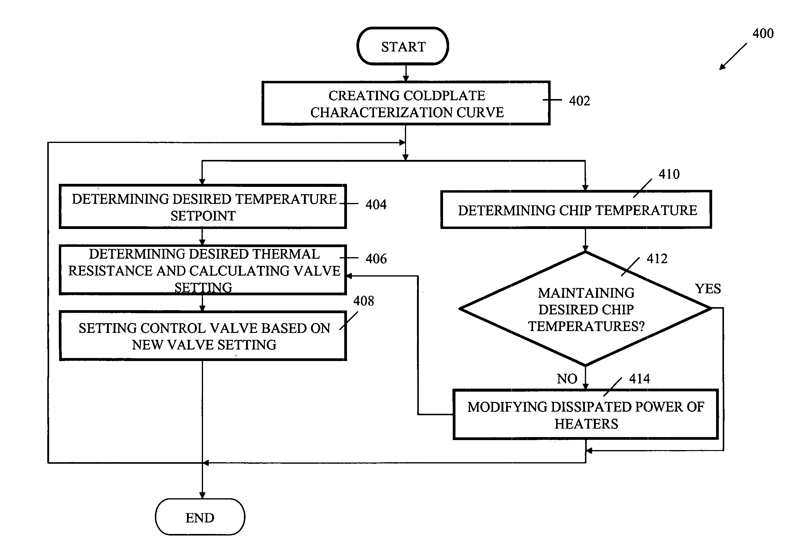
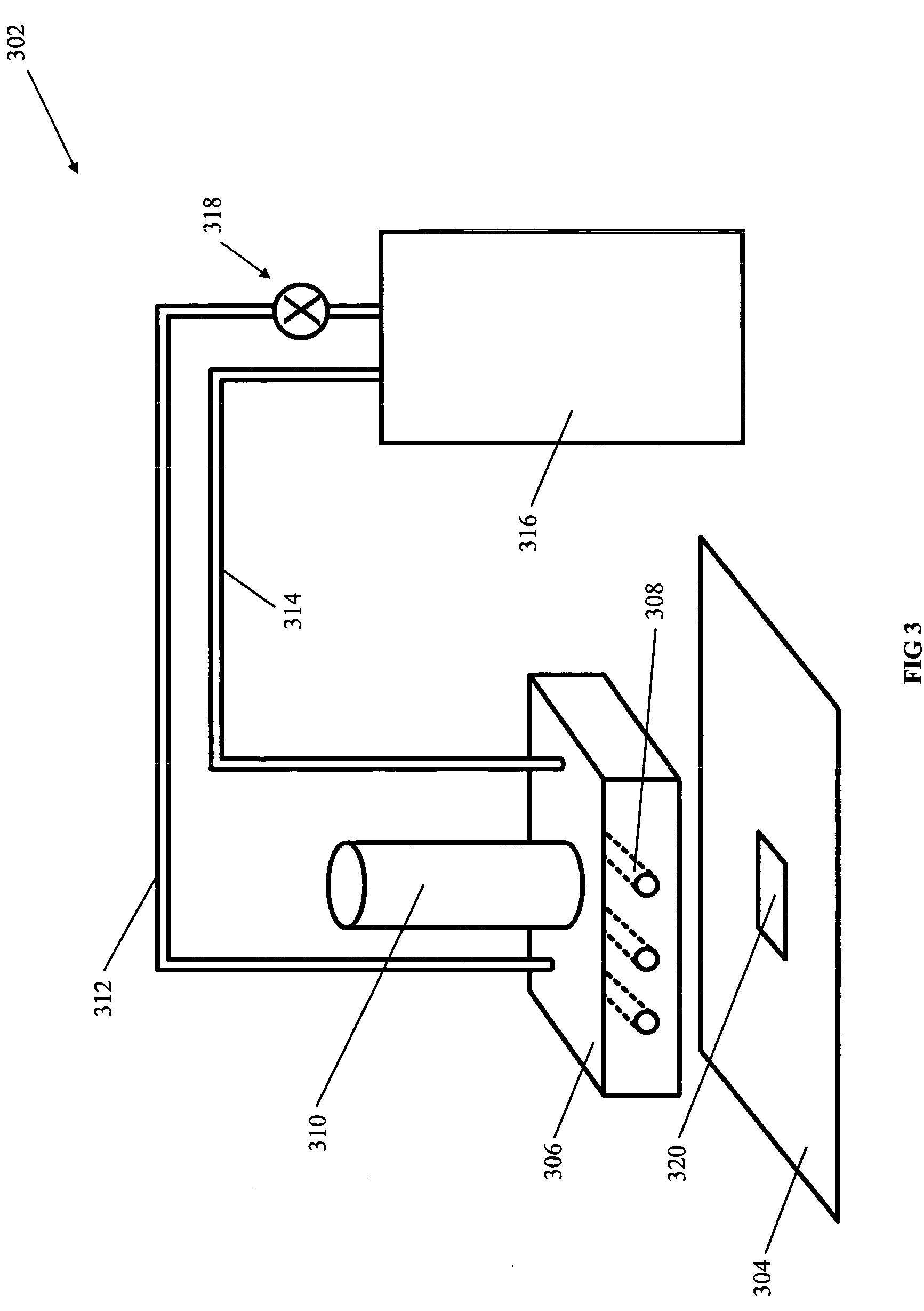
[0015] A system, apparatus and method for controlling temperature of an integrated circuit in a chip tester is disclosed. Embodiments include supplying a chilled fluid to a cold plate at a first flowrate, where the first flowrate is associated with a first valve setting based on at least a desired temperature setpoint and an applied power. Embodiments may determine ...


PUM


Abstract

A system, apparatus and method for controlling temperature of an integrated circuit in a chip tester is disclosed. Embodiments include supplying a chilled fluid to a cold plate at a first flowrate, where the first flowrate is associated with a first valve setting based on at least a desired temperature setpoint and an applied power. Embodiments may determine a change in applied power and modify the chilled fluid flowrate in response to a change in testing conditions to a second flowrate associated with a second valve setting associated with at least the desired temperature setpoint and the changed testing conditions. This feed forward loop may be supplemented by a feedback loop that includes modifying the energy supplied to a cold plate heater in response to a comparison of a current temperature and the temperature setpoint. The valve may be a proportional control valve or the like.

Description

FIELD OF INVENTION [0001] The present invention is in the field of temperature control of a system. More particularly, the present invention relates to temperature control in an integrated circuit processing and testing system. BACKGROUND [0002] High performance processor chips, which are also known as microchips or integrated circuits (ICs), are often tested and subsequently sorted based on their performance and matched to a given class of machine. Individual chips are tested prior to installation on modules in machines in order to identify chip failures, allowing higher machine manufacturing productivity and improving product quality. Test equipment developed to support performance, productivity and quality is usually required to meet functional test limits defined by several boundary variables such as chip / module voltage, clock speed, power dissipation, and temperature. [0003] Chip testers such as functional or non-functional testers may detect chip failures during testing at dif...

Claims


Application Information

Patent Timeline
Patent Type & Authority Applications(United States)
IPC IPC(8): G01R31/02
CPCG01R31/2874
Inventor BEAMAN, DANIEL PAULFLORENCE, ROBERT F. JR.MAHANEY, HOWARD VICTOR JR.WRIGHT, FREDERIC WILLIAM IV
Owner GOOGLE LLC
Learn More