Electronically controlled diaphragm pump

a diaphragm pump, electronic control technology, applied in the direction of pump control, positive displacement liquid engine, biochemistry apparatus, etc., can solve the problem that no such diaphragm pump is known or availabl

Inactive Publication Date: 2011-09-15
STOBBE TECH
View PDF19 Cites 41 Cited by
  • Summary
  • Abstract
  • Description
  • Claims
  • Application Information

AI Technical Summary

Problems solved by technology

Despite the many products available around the globe and the comprehensive prior art, no such diaphragm pump is known or available.

Method used


Image

  • Electronically controlled diaphragm pump
  • Electronically controlled diaphragm pump
  • Electronically controlled diaphragm pump

Examples


first embodiment

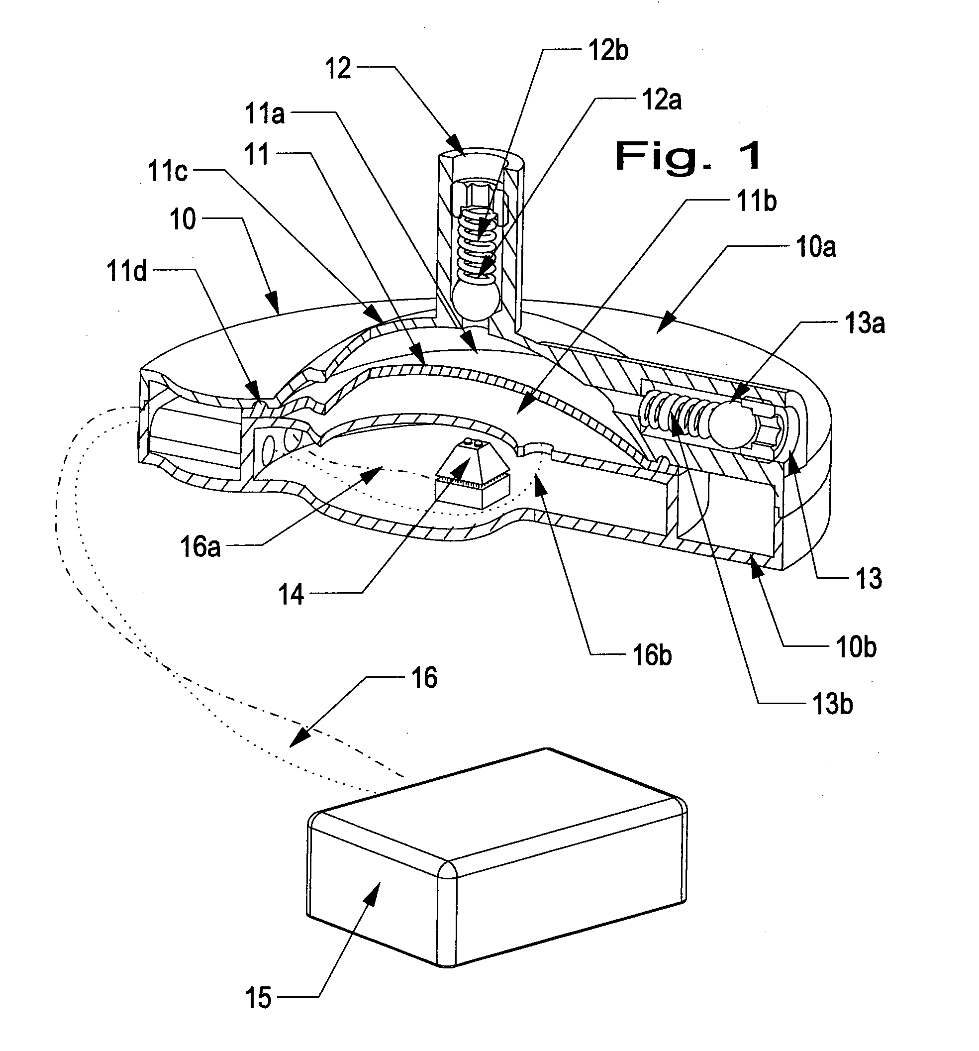
[0181]FIG. 1 shows a stand-alone reciprocating membrane pump 10, which may comprise single-use materials, and which has a single diaphragm 11, operating actions being by pneumatics, which may be from absolute pressure to over atmospheric pressure, the pump being micro processor controlled with various sensors and principles, and in its most simple form with two spring loaded plunger body check valves 12a, 13a in the fluid stream.

[0182]The flexible diaphragm 11 may be of circular shape and enclosed at the circumference in order to seal each side of the diaphragm from access to the other diaphragm side within the housing. The diaphragm 11 circumference shape is compatible with the recess 11d in the housing parts 10a, 10b. One side of the diaphragm 11 is exclusively in contact with the fluid 11a to be pumped, and the other side exclusively in contact with the drive gas 11b. At least one side of the diaphragm house 11c is of concave design.

[0183]The fluid / media side 11a of the diaphragm...

second embodiment

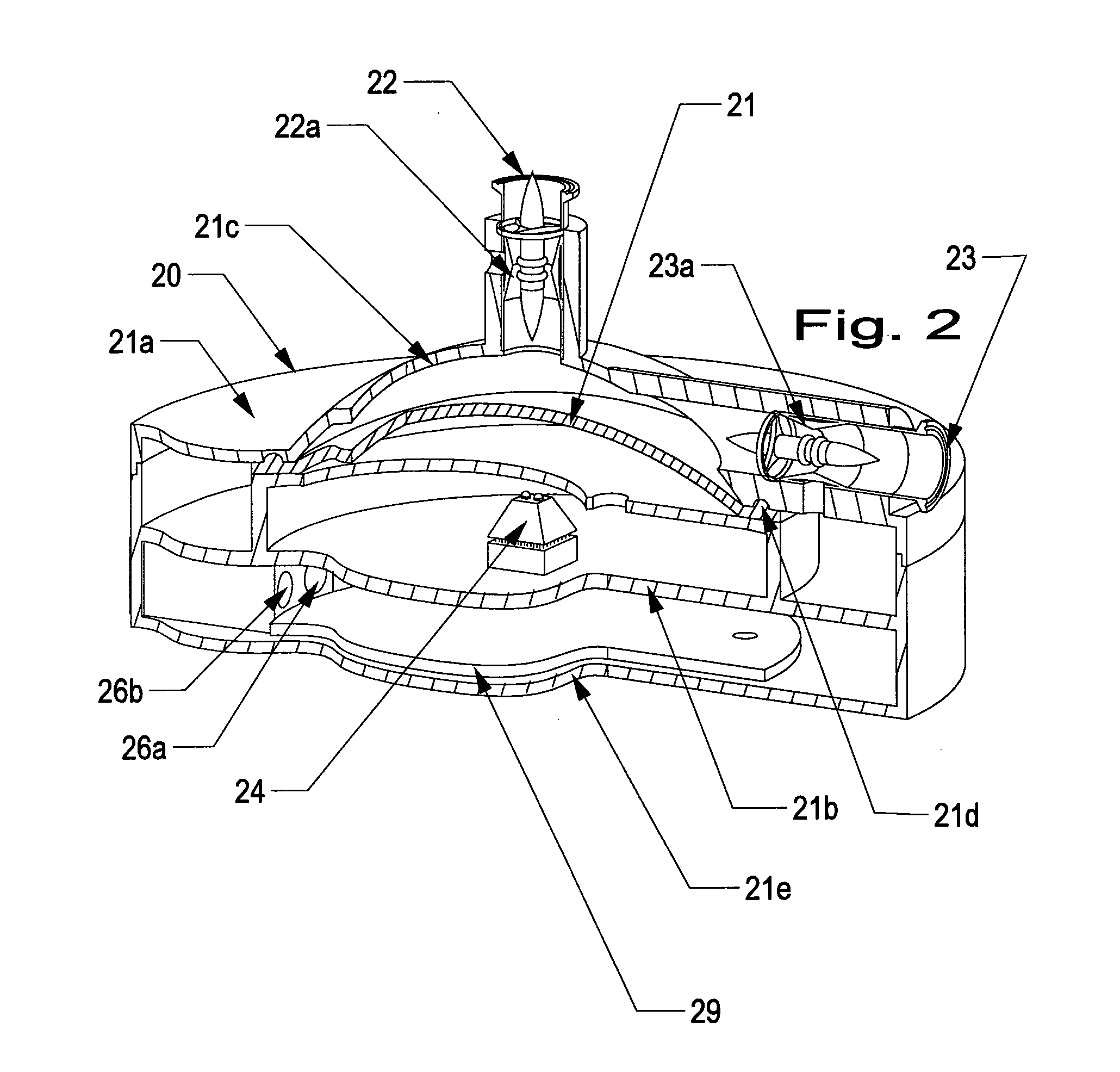
[0186]FIG. 2 shows a stand-alone reciprocating membrane pump 20, which may comprise single-use materials, a which has single diaphragm 21, the operating actions being by pneumatics, which may be from absolute pressure to over atmospheric pressure, the pump being micro processor controlled with various sensors and principles, and in its most simple form with two expansible tube valves 22a, 23a in the fluid stream.

[0187]The pump of FIG. 2 has two rigid housing parts 21b, 21c on each side of the flexible diaphragm 21, and assembled on the circumference. The pump 20 also includes a PCB 29 (no electronic parts shown) arranged at the bottom house part 21e. The diaphragm membrane 21 comprises a cast on half O-ring on the diaphragm circumference, which act as the sealing element in the recess 21d on housing part 21a. Diaphragm control is in principle similar to the pump of FIG. 1, the difference being the introduction of expansible tube valves 22a, 23a for extended control of fluid flow. Th...

third embodiment

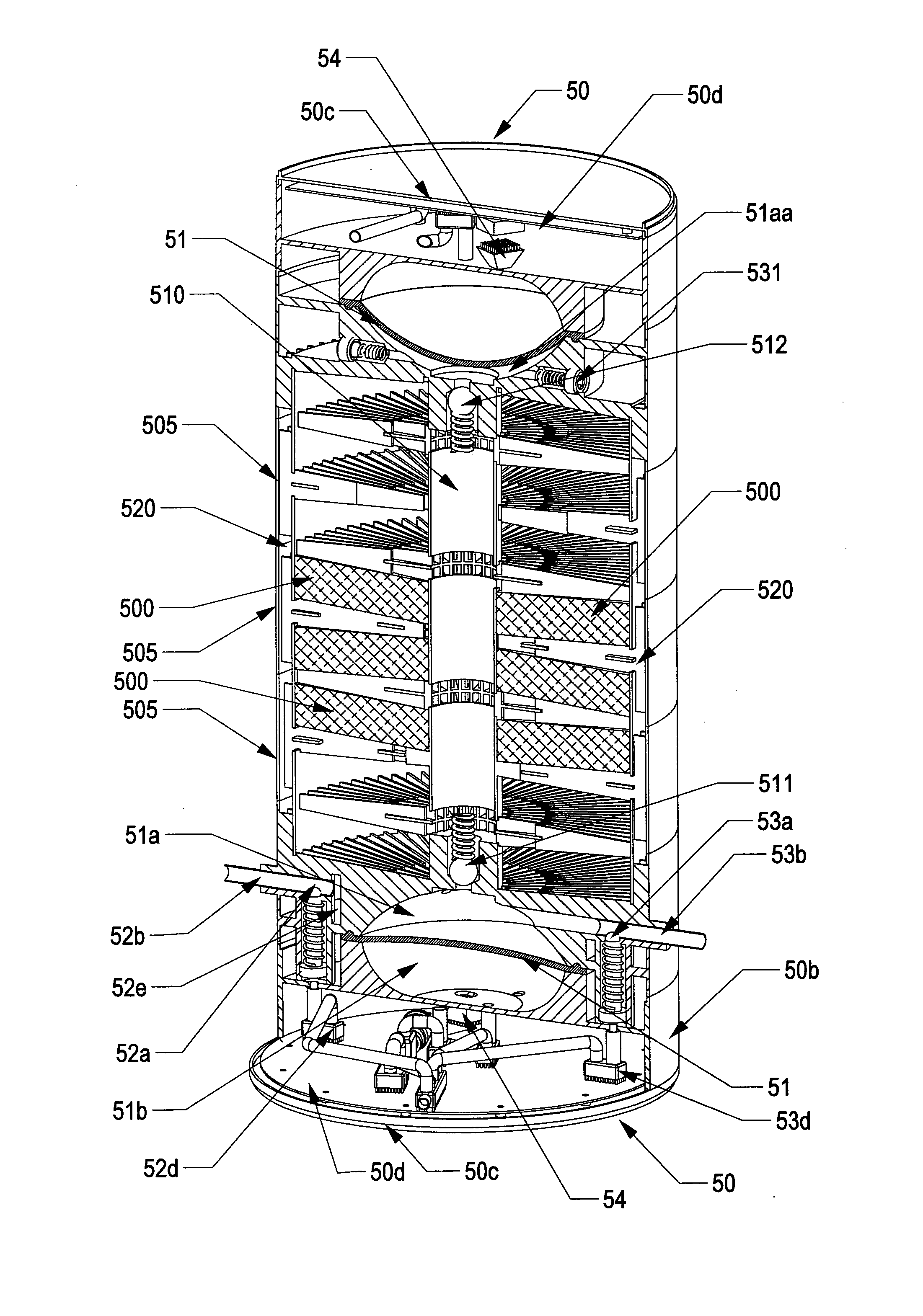
[0188]FIG. 3 shows a pump system of the invention. The system shown in FIG. 3 is a stand-alone system with two membrane diaphragm pumps, which may comprise single-use materials, the operating actions being by pneumatics, which may be from absolute pressure to over atmospheric pressure, the pump being micro processor controlled with various sensors and principles, and in its most simple form with electronically controlled valves, which may be tube sleeve valves, in the fluid stream. Two individual pumps 30, 300 are assembled with back to back for compactness.

[0189]Gas pressure on the drive sides 31b, 311b of the diaphragm 31, 311 is regulated by proportional valves. Absolute pressure sensors may measure in real-time the actual gas pressure in both drive chambers 31b, 311b, and fluid in fluid chambers 31a, 311a may be forced in direction according to programming. The position of each diaphragm 31, 311 is measured by a corresponding displacement sensor 34, 344 and information from the ...


PUM

PropertyMeasurementUnit
diameteraaaaaaaaaa
diameteraaaaaaaaaa
diameteraaaaaaaaaa

Abstract

An electronically controlled diaphragm pump system is provided. The pump systems comprises a pump housing with a drive gas chamber and a fluid chamber separated by a diaphragm. The drive gas chamber is connected to one or more gas ports for injecting and / or sucking a gas into and out of the gas chamber. The fluid chamber is connected to a least one port for fluid inlet and at least one port for fluid outlet, where the inlet port has a valve adapted to open for fluid inlet when gas is sucked out of the gas chamber and the outlet port has a valve adapted to open for fluid outlet when gas is injected into the gas chamber. The pump system further has gas pressure means connected to a gas inlet port for providing a drive gas pressure in response to a control signal, and gas under-pressure means connected to a gas outlet port for providing a gas under-pressure or sucking of gas in response to a control signal. Furthermore, the pump system has a displacement sensor for detecting displacement or position of the diaphragm, and control circuitry connected to the displacement sensor for determining the displacement or position of the diaphragm and adapted for supplying the control signals to the gas pressure means and the gas under-pressure means. It is preferred that the means for providing a drive gas pressure comprises a gas-pressure proportional control valve being connected to the gas port and the control circuitry, whereby the drive gas pressure is varied as a function of the control signal supplied by the control circuitry. Also the means for providing a gas under-pressure may comprise a gas-under proportional control valve for controlling the gas under-pressure as a function of the control signal supplied by the control circuitry.

Description

TECHNICAL FIELD[0001]The present invention relates to a diaphragm pump, which may be fully electronically controlled and driven by pneumatics. The pump may be suitable for circulation of critical fluids in the chemical or pharmaceutical industry, and parts of the pump having media or fluid contact may be manufactured from disposable materials.BACKGROUND OF THE INVENTION[0002]The disposable bioreactors were considered a novelty, and perhaps even a passing trend, as recently as mid 90ties. As single-use bioreactors have matured and begun to address most of these issues, their market acceptance has rapidly expanded. The move to disposable bioreactors is, in many instances, driven by reduction in sterilisation and cleaning requirements, improved plant flexibility, reduced costs and faster time to market for the end product. All of these benefits have been recently documented. These hurdles include the ability to add reliable, accurate, low cost sensors and pumping devices so that standa...

Claims


Application Information

Patent Timeline
Patent Type & Authority Applications(United States)
IPC IPC(8): F04B49/06C12Q3/00
CPCC12M23/34C12M23/42C12M25/14F04B43/0736F04B43/073F04B43/0733F04B43/0081F04B45/0536C12M29/00F04B49/06F04B49/08
Inventor STOBBE, PER
Owner STOBBE TECH
Why Eureka
Try Eureka