Diaphragm pump
a diaphragm pump and pump body technology, applied in the direction of pump components, positive displacement liquid engines, liquid fuel engine components, etc., can solve the problems of difficult to be driven out, difficulty in discharge, and inconvenience of conventional air-cooling type cooling system, so as to facilitate the discharge of bubbles, reduce the loss of pressure, and reduce the effect of pressure loss
- Summary
- Abstract
- Description
- Claims
- Application Information
AI Technical Summary
Benefits of technology
Problems solved by technology
Method used
Image
Examples
first exemplary embodiment
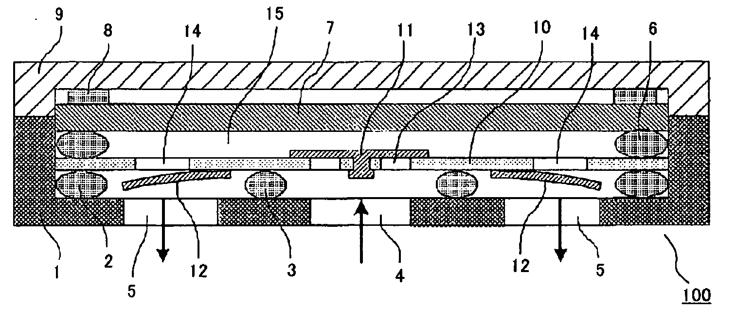
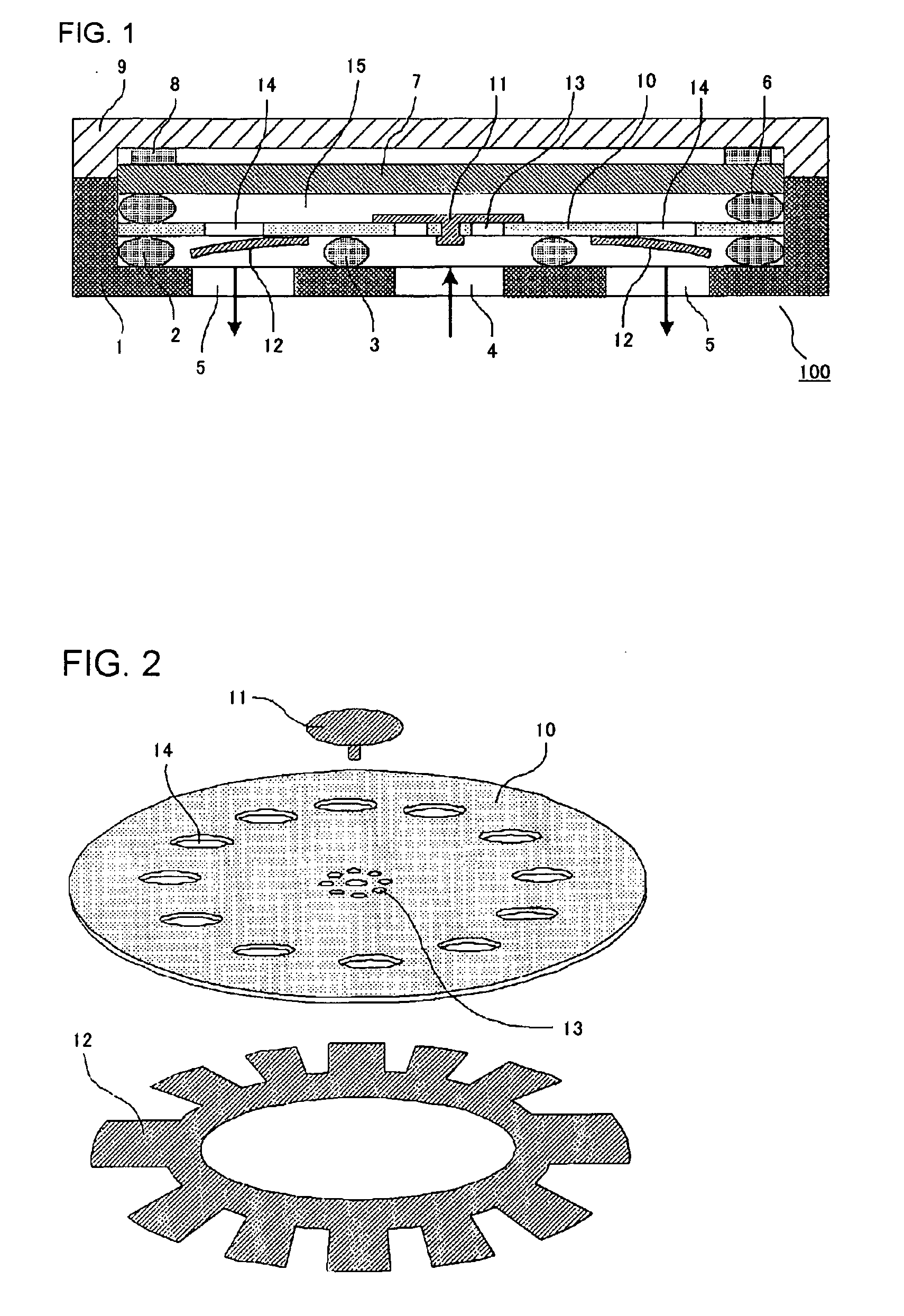
[0027]FIG. 1 is a cross-sectional view showing a piezoelectric pump according to a first exemplary embodiment of the present invention, and FIG. 2 is an exploded perspective view showing a valve main plate 10 and a check valve (inflow check valve 11 and outflow check valve 12), constituting an essential portion of the piezoelectric pump.
[0028]In FIGS. 1 and 2, the numeral 1 designates a pump casing, 2 a pump outlet port anti-leak partition seal, 3 a pump inlet port partition seal, 4 a pump inlet port, 5 a pump outlet port, 6 a pump chamber anti-leak partition seal, 7 a piezoelectric vibrator, 8 a vibrator dumper, 9 a pump cover, 10 the valve main plate, 11 the inflow check valve, 12 the outflow check valve, 13 an inlet port, 14 an outlet port, and 15 a pump chamber.
[0029]In the piezoelectric pump shown in FIG. 1, the piezoelectric vibrator 7 flexurally vibrates, once an electric field is applied thereto. At the moment the piezoelectric vibrator 7 deforms so as to protrude upward, th...
second exemplary embodiment
[0031]FIGS. 5(a) and 5(b) are plan views from the top and the bottom respectively, showing the valve main plate 10 according to a second exemplary embodiment of the present invention. In FIGS. 5(a) and 5(b), the same constituents as those of the foregoing embodiment shown in FIGS. 1 and 2 are given the same numerals, and the duplicating description will not be repeated. The pump chamber of the piezoelectric pump according to the foregoing embodiment has a circular transverse cross-section, and accordingly the valve main plate is also circular, however in this embodiment those are of a square shape with rounded corners. In this embodiment, the outlet ports 14 are of a shape similar to an isosceles triangle and located at the four corners of the valve main plate, while the configuration of the remaining portion is the same as that of the first exemplary embodiment, and the inflow check valve 11 which opens and closes the inlet port 13 is constituted of a resin film, and the outflow ch...
third exemplary embodiment
[0033]FIG. 6 is an exploded perspective view showing a valve main plate 10 and check valves 11, 22 according to a third exemplary embodiment of the present invention. As shown therein, the outlet port 14 is a generally elliptical slot, and provided in a plurality of numbers along the outer wall of the pump chamber. Such slot shape contributes to increasing the area of the outlet port, thereby facilitating discharging the bubble that has intruded into the pump chamber. The outflow check valve 22 for opening and closing the outlet port 14 of such slot shape may be constituted of a resin film which has a low elastic modulus and tightly sticks to the valve main plate (for example, fluoric resin, ethylene propylene rubber (EPDM), silicone rubber, polyimide resin and so on) of approx. 0.1 to 0.5 mm in thickness, and is formed in a generally circular ring shape. FIGS. 7(a) and (b) are cross-sectional views respectively showing a closed state and an open state of the outflow check valve 22....
PUM
 Abstract
Description
Claims
Application Information
 - R&D
- Intellectual Property
- Life Sciences
- Materials
- Tech Scout
- Unparalleled Data Quality
- Higher Quality Content
- 60% Fewer Hallucinations
Browse by: Latest US Patents, China's latest patents, Technical Efficacy Thesaurus, Application Domain, Technology Topic, Popular Technical Reports.
© 2025 PatSnap. All rights reserved.Legal|Privacy policy|Modern Slavery Act Transparency Statement|Sitemap|About US| Contact US: help@patsnap.com


