Motor/Pump Assembly

a technology of motors and components, applied in the direction of positive displacement liquid engines, vehicle sub-unit features, braking systems, etc., can solve the problems of high equipment expenditure, high noise, and high maintenance costs of pumps, and achieve the effect of preventing the development of exhaust noise and low nois

Inactive Publication Date: 2010-02-25
CONTINENTAL TEVES AG & CO OHG
View PDF4 Cites 39 Cited by
  • Summary
  • Abstract
  • Description
  • Claims
  • Application Information

AI Technical Summary

Benefits of technology

[0011]According to one aspect of the invention, the foregoing object is achieved in that the outlet channels in the covers of the working chamber and in the pump housing are arranged in such a fashion that air displaced from the working chambers is routed into an inside space of the pump housing, and that an air outlet unit is provided which allows exhausting the air from the inside space at low noise. The inside space, also referred to as crank chamber, thus serves as a sound absorbing space since the exhausted air is not routed directly into the atmosphere, thus preventing the development of exhaust noise.

Problems solved by technology

Due to their principle, these pumps suffer from much friction and need lubrication in order to reach an acceptable useful life.
Nevertheless, an appreciable portion of the power output by the internal combustion engine is required for driving a pump of this type.
It may involve great expenditure to equip such an electrically driven pump with a lubricant cycle or to connect it to such a cycle.
To this end, the self-lubricating material graphite is employed in vane-type pumps, and the vanes are made from this material with the necessary precision and requiring great expenditure.
These requests cannot be satisfied by the prior art diaphragm pumps due to vibrations or necessitate great expenditure in sound absorbing measures, respectively.

Method used


Image

  • Motor/Pump Assembly
  • Motor/Pump Assembly
  • Motor/Pump Assembly

Examples


first embodiment

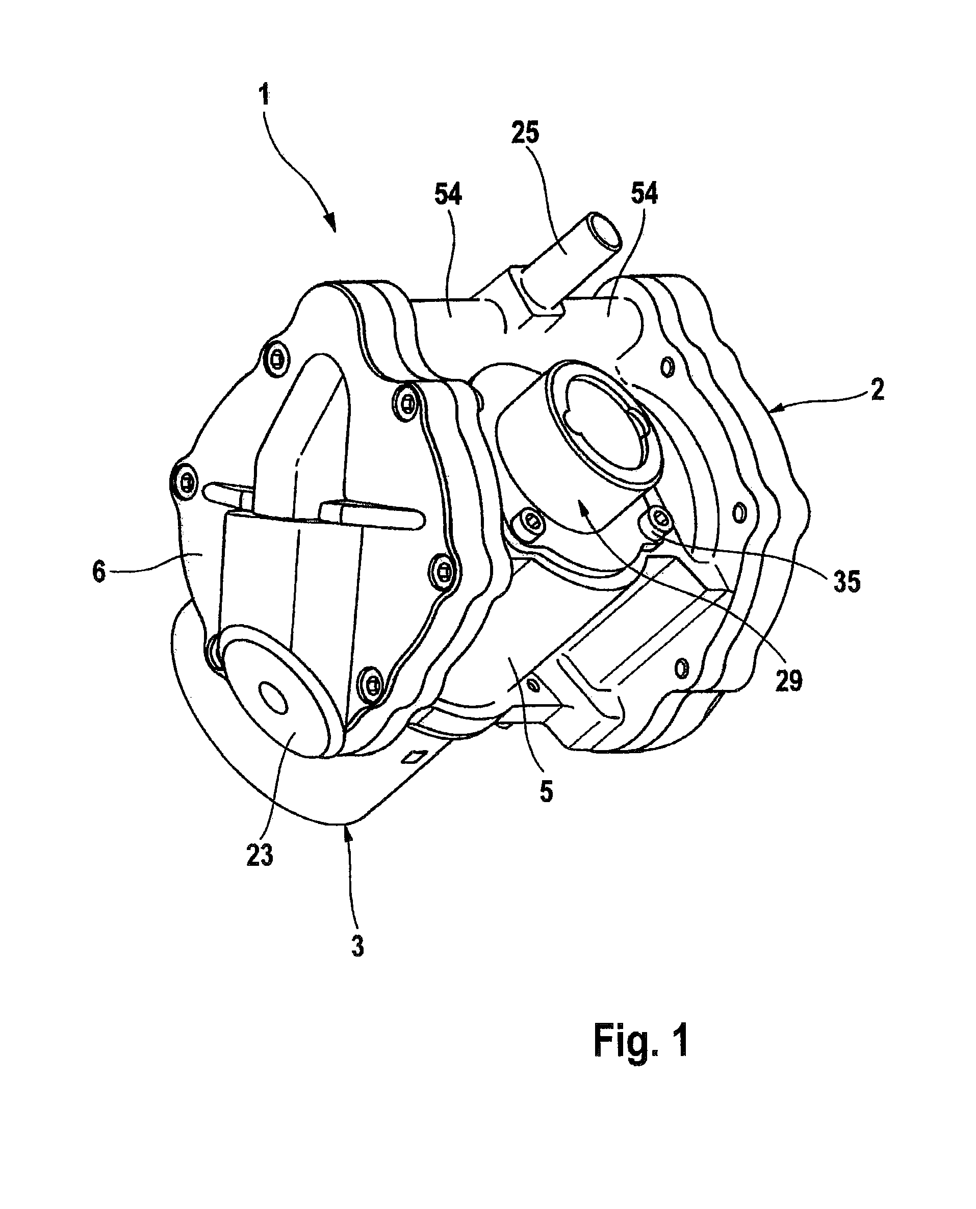
[0054]FIG. 1 shows a three-dimensional view of a motor-and-pump assembly 1 of the invention which is provided, for example, for supplying vacuum for a brake actuating device of a motor vehicle brake system with a pneumatic brake booster (not shown). The motor-and-pump assembly 1 comprises a pump 2 with a pump housing 5 and an electric motor 3 which drives the pump 2 and can e.g. be designed as a direct-current motor.

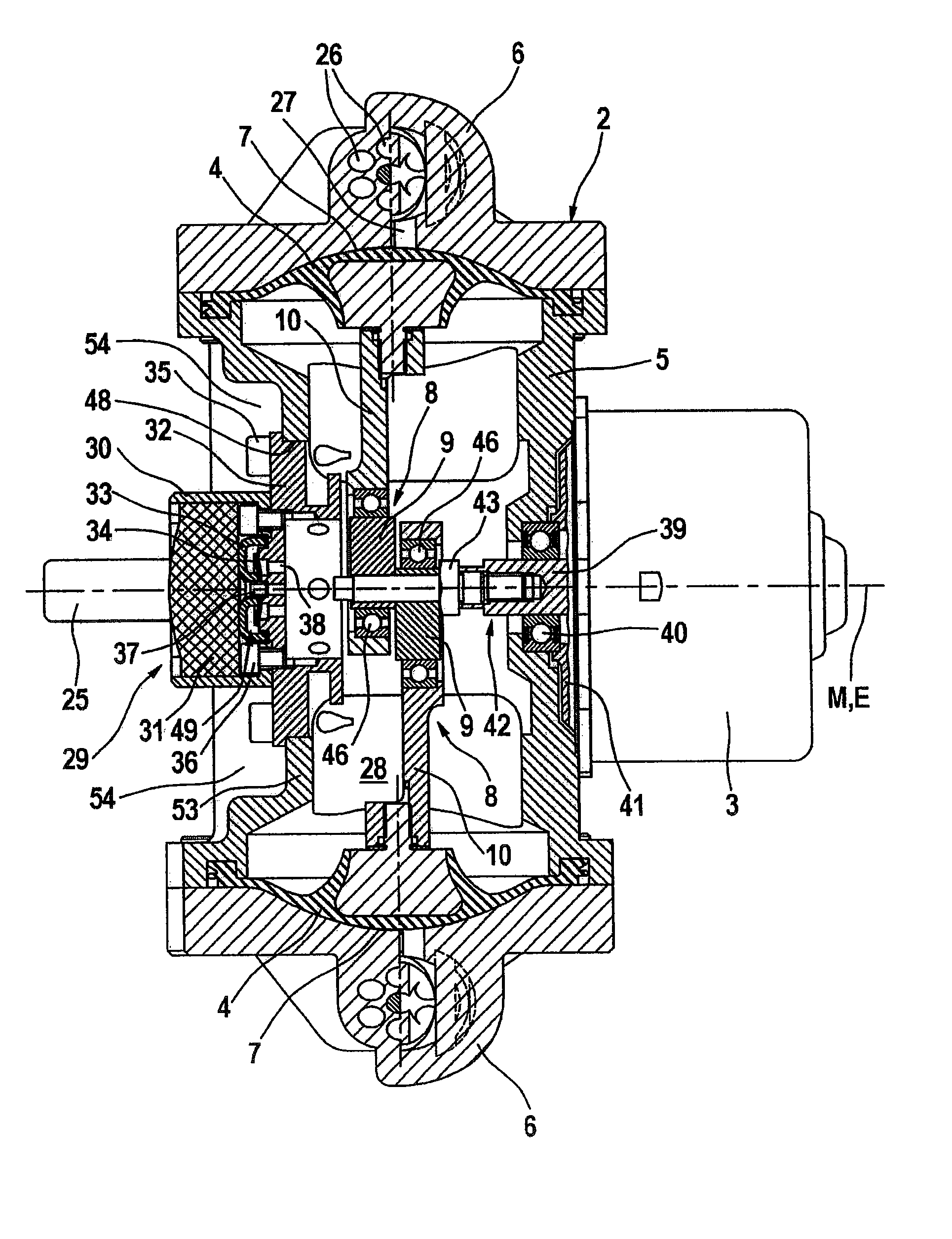
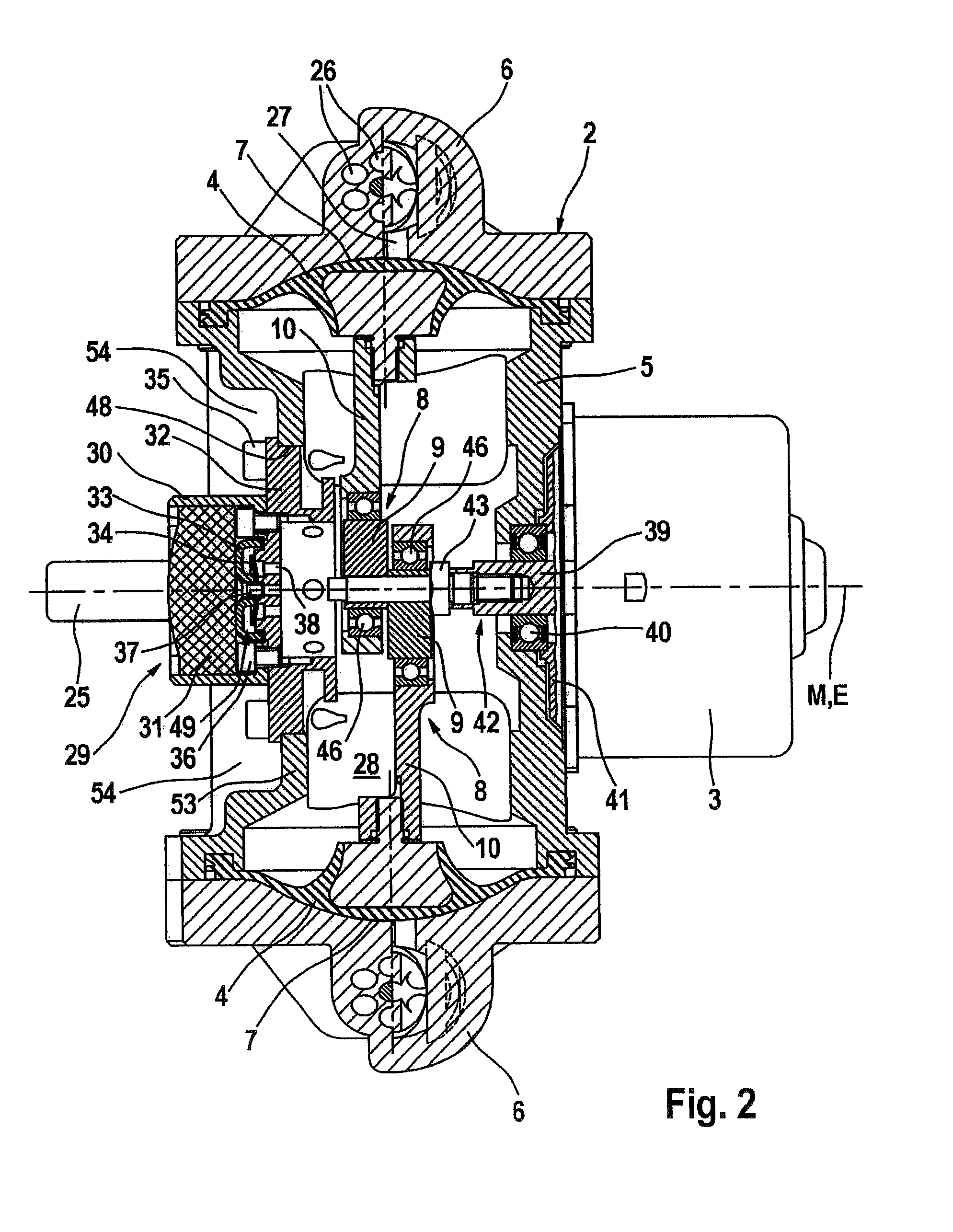
[0055]As can be taken from FIG. 2 in particular which shows the motor-and-pump assembly in the longitudinal cross-section taken through a first plane, pump 2 is designed as a double diaphragm pump with two opposite working diaphragms 4 being compressed in each case between the pump housing 5 and a working chamber cover 6, thereby delimiting a working chamber 7. The working diaphragms 4 are movable in an opposite direction by means of a crank drive 8, which comprises an eccentric 9 and a connecting rod 10 per working diaphragm 4.

[0056]As can be seen in FIG. 3, which illus...

second embodiment

[0094]FIG. 4 is a three-dimensional view of the motor-and-pump assembly 101, which comprises a pump 102 with a pump housing 105 and an electric motor 103 driving the pump 102, and the motor 103 can be designed as a direct-current motor, for example.

[0095]As is apparent from FIG. 5 in particular, which shows the motor-and-pump assembly 101 in a longitudinal cross-section taken through a first plane, the pump 102 is provided as a double diaphragm pump with two opposed working diaphragms 104, being compressed in each case between the pump housing 105 and a working chamber cover 106 and thereby delimiting a working chamber 107. The working diaphragms 104 are movable in opposite directions by means of a crank drive 108 which comprises an eccentric 109 and a connecting rod 110 per working diaphragm 104.

[0096]FIG. 6 is a cross-sectional view of the working chamber cover 106 of the motor-and-pump assembly 101. It is apparent that the working chamber cover 106 includes an upper lid 155 and a...


PUM


Abstract

A motor and pump assembly for providing pressure to a brake actuating device of a motor vehicle brake system is described herein. The assembly comprises an electric motor and a double diaphragm pump. The pump includes a pump housing, two opposed working diaphragms, and crank drives each being coupled between the electric motor and a respective diaphragm for moving the diaphragm. A working chamber is defined between the pump housing and a working chamber cover. Each working chamber including an inlet channel, an inlet valve associated with the inlet channel, an outlet channel, and an outlet valve associated with the outlet channel, wherein the outlet channels are defined in the covers of the working chamber and in the pump housing to direct air displaced from the working chambers into an inside space of the pump housing. An air outlet unit is provided for exhausting the air from the inside space.

Description

CROSS-REFERENCE TO RELATED APPLICATIONS[0001]This application is the U.S. national phase application of PCT International Application No. PCT / EP2007 / 050913, filed Jan. 30, 2007, which claims priority to German Patent Application No. DE0102006006493.3, filed Feb. 10, 2006 and German Patent Application No. DE102007005223.7, filed Jan. 29, 2007, the contents of such applications being incorporated by reference herein in their entirety.BACKGROUND OF THE INVENTION[0002]1. Field of the Invention[0003]The present invention relates to a motor-and-pump assembly, in particular for providing pressure for a brake actuating device of a motor vehicle brake system.[0004]2. Description of the Related Art[0005]To make vacuum available for a pneumatic brake booster whose interior is subdivided into at least one vacuum chamber and one working chamber, vacuum pumps are typically employed which aspirate residual air out of the vacuum chamber and exhaust it into the atmosphere. Vane-type pumps or wing pu...

Claims


Application Information

Patent Timeline
Patent Type & Authority Applications(United States)
IPC IPC(8): B60T13/16F04B43/04
CPCB60T17/02F04B45/047F04B45/043F04B39/0061B60T17/008B60T13/52B60Y2400/81
Inventor SCHONLAU, JURGENRUFFER, MANFREDRITTER, WOLFGANGSEITZ, KARLHEINZDRUMM, STEFANGONZALEZ, JOSEJURGING, MICHAELGUDE, DANIELAVOLKERING, OLIVER
Owner CONTINENTAL TEVES AG & CO OHG
Why Eureka
Try Eureka