
Method and system for controlling a downhole flow control device using derived feedback control

a flow control and feedback control technology, applied in the direction of survey, sealing/packing, borehole/well accessories, etc., can solve the problems of reducing the reliability of the overall system, reducing the effective lifespan of the downhole electronics, and not being able to confirm the devi

Inactive Publication Date: 2004-05-18
BAKER HUGHES HLDG LLC
View PDF7 Cites 43 Cited by
  • Summary
  • Abstract
  • Description
  • Claims
  • Application Information

AI Technical Summary

Problems solved by technology

The control of oil and gas production wells constitutes an on-going concern of the petroleum industry due, in part, to the enormous monetary expense involved in addition to the risks associated with environmental and safety issues.
The principal problem with this arrangement is that there is no way to confirm that the device has actually performed the desired action.
However, the combination of high pressure and high temperature act to reduce the effective lifespan of the downhole electronics and reduce the reliability of the overall system.
For example, hydraulic fluid ages and exhibits reduced lubricity with exposure to high temperature; scale and other deposits will occur in the interior of the valve; and seals will degrade and wear with time.

Method used


Image

  • Method and system for controlling a downhole flow control device using derived feedback control
  • Method and system for controlling a downhole flow control device using derived feedback control
  • Method and system for controlling a downhole flow control device using derived feedback control

Examples


Embodiment Construction

As is known, a given well may be divided into a plurality of separate zones which are required to isolate specific areas of a well for purposes of producing selected fluids, preventing blowouts and preventing water intake.

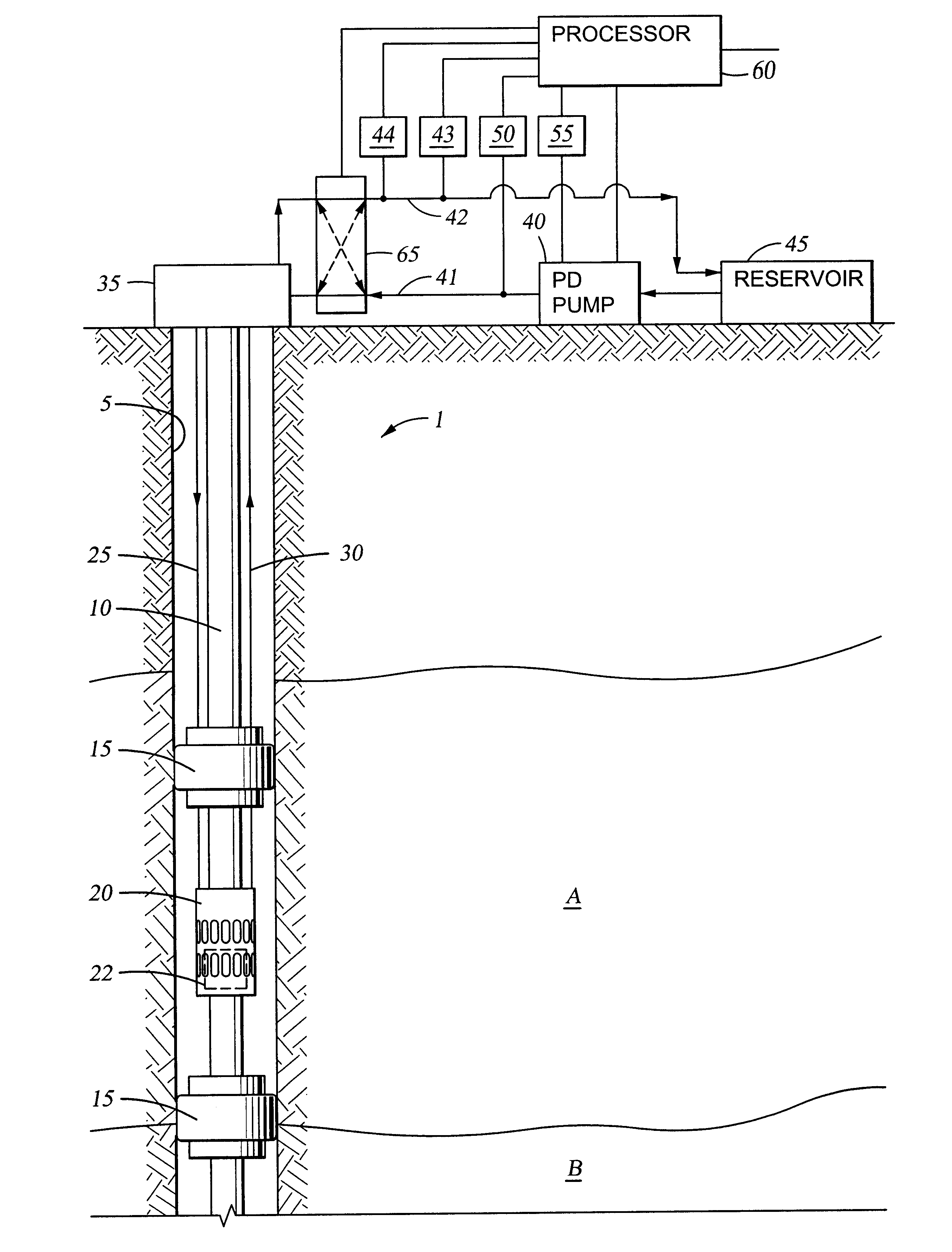
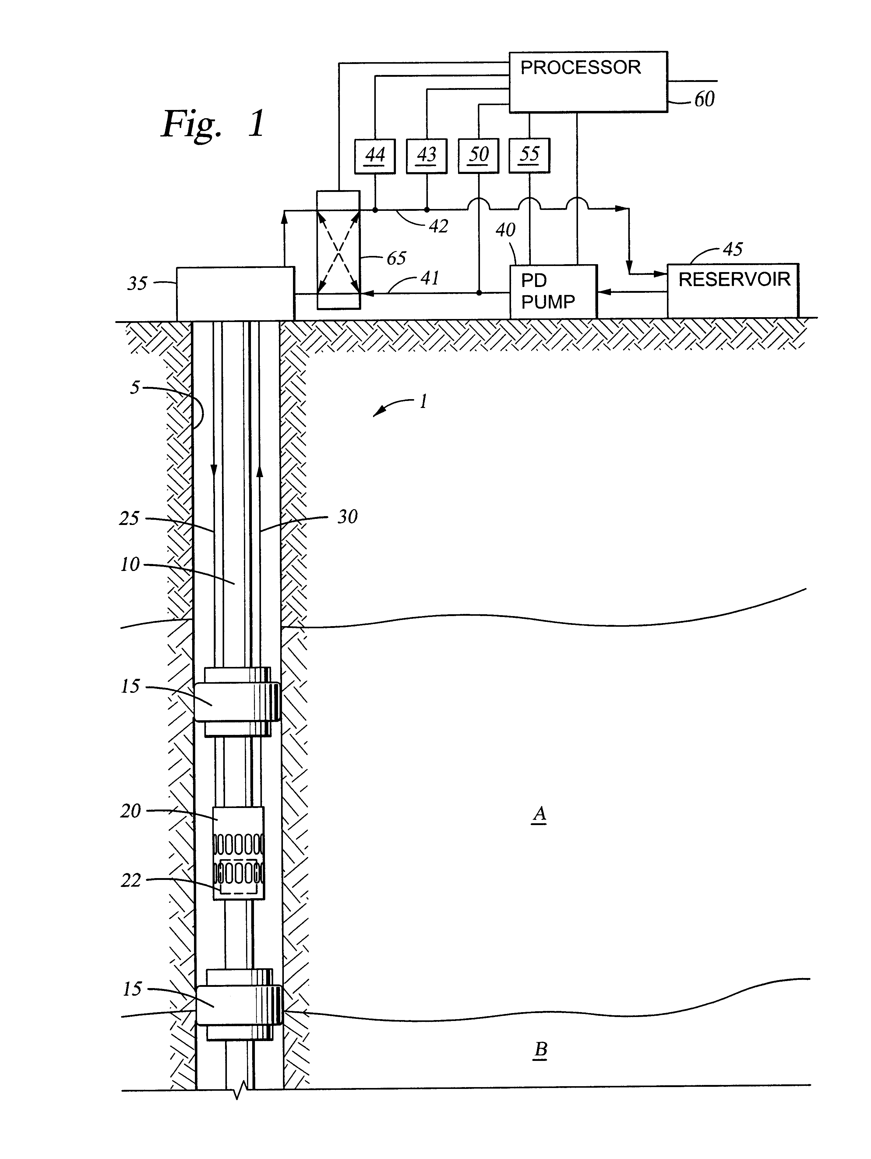
With reference to FIG. 1, well 1 includes two zones, namely zone A and zone B where the zones are separated by an impermeable barrier. Each of zones A and B have been completed in a known manner. FIG. 1 shows the completion of zone A using packers 15 and sliding sleeve valve 20 supported on tubing string 10 in wellbore 5. The packers 15 seal off the annulus between the wellbore and a flow control device, such as sliding sleeve valve 20, thereby constraining formation fluid to flow only through an open sliding sleeve valve 20. Alternatively, the flow control device may be any flow control device having at least one moveable element for controlling flow, including, but not limited to, a downhole choke and a downhole safety valve. As is known in the art, a common slid...


PUM


Abstract

A system and methods for proportionally controlling hydraulically actuated downhole flow control devices using derived feedback control. The system comprises a downhole flow control device with a moveable element in a stationary housing. The moveable element is actuated by a balanced hydraulic piston. Hydraulic lines are fed to either side of the piston to effect actuation in either direction. A processor controlled, surface mounted hydraulic system supplies fluid to the piston. A pressure sensor measures supply pressure to the piston and a cycle counter indicates pump cycles and both sensors generate outputs to the processor. The downhole moveable element is cycled between end stops until successive moveable element breakout pressures are within a predetermined value as measured by the surface pressure sensor. A relationship is then derived between moveable element movement and pumped fluid volume and the relationship is used to move the moveable element to a predetermined position to control flow.

Description

1. Field of the InventionThis invention relates generally to a method for the control of oil and gas production wells. More particularly, it relates to proportional control of movable elements in well production flow control valves.2. Description of the Related ArtThe control of oil and gas production wells constitutes an on-going concern of the petroleum industry due, in part, to the enormous monetary expense involved in addition to the risks associated with environmental and safety issues. Production well control has become particularly important and more complex in view of the industry wide recognition that wells having multiple branches (i.e., multilateral wells) will be increasingly important and commonplace. Such multilateral wells include discrete production zones which produce fluid in either common or discrete production tubing. In either case, there is a need for controlling zone production, isolating specific zones and otherwise monitoring each zone in a particular well. ...

Claims


Application Information

Patent Timeline
Patent Type & Authority Patents(United States)
IPC IPC(8): E21B34/16E21B34/10E21B34/00F15B15/28F15B15/00F15B19/00E21B44/00
CPCE21B34/10E21B34/16E21B44/00F15B15/2838F15B19/002
Inventor BUSSEAR, TERRYGOING, WALTERSCHNEIDER, DAVIDNORRIS, MIKE
Owner BAKER HUGHES HLDG LLC
Learn More