Inductively coupled direct contact test probe

a direct contact, test probe technology, applied in the direction of resistance/reactance/impedence, frequency measurement arrangement, instruments, etc., can solve the problems of insufficient accuracy to locate the emi signal on the circuit, cumbersome use, inductive coupling path, etc., to minimize the pickup of unwanted electromagnetic signals without risk of damage

Active Publication Date: 2005-01-11
DELL PROD LP
View PDF2 Cites 21 Cited by
  • Summary
  • Abstract
  • Description
  • Claims
  • Application Information

AI Technical Summary

Benefits of technology

A technical advantage of the present invention is that it combines the usefulness of the near field probe and the preciseness of the oscilloscope probe without the potential for grounding out (shorting) to nearby circuits. Another technical advantage is the ability to contact high voltage circuits without the risk of damaging the measuring equipment because the probe is isolated from the input of the measurement instrument. Another technical advantage is providing calibrated, repea

Problems solved by technology

A disadvantage of the current clamp probe is that it requires an inductively coupled path (must encircle) with the wire or cable carrying the signal of interest.
A disadvantage is that it is only useful in finding the general location of EMI, but it is not precise enough to locate the EMI signal on the circuit, such as a specific signal pin or signal line location.
The oscilloscope probe can measure the RF signal precisely, and can be post processed at the oscilloscope to show frequency (EMI) data, but it is cumbersome to use due to the need for a direct connection to the circuit under test and a nearby connection to

Method used


Image

  • Inductively coupled direct contact test probe
  • Inductively coupled direct contact test probe
  • Inductively coupled direct contact test probe

Examples


Embodiment Construction

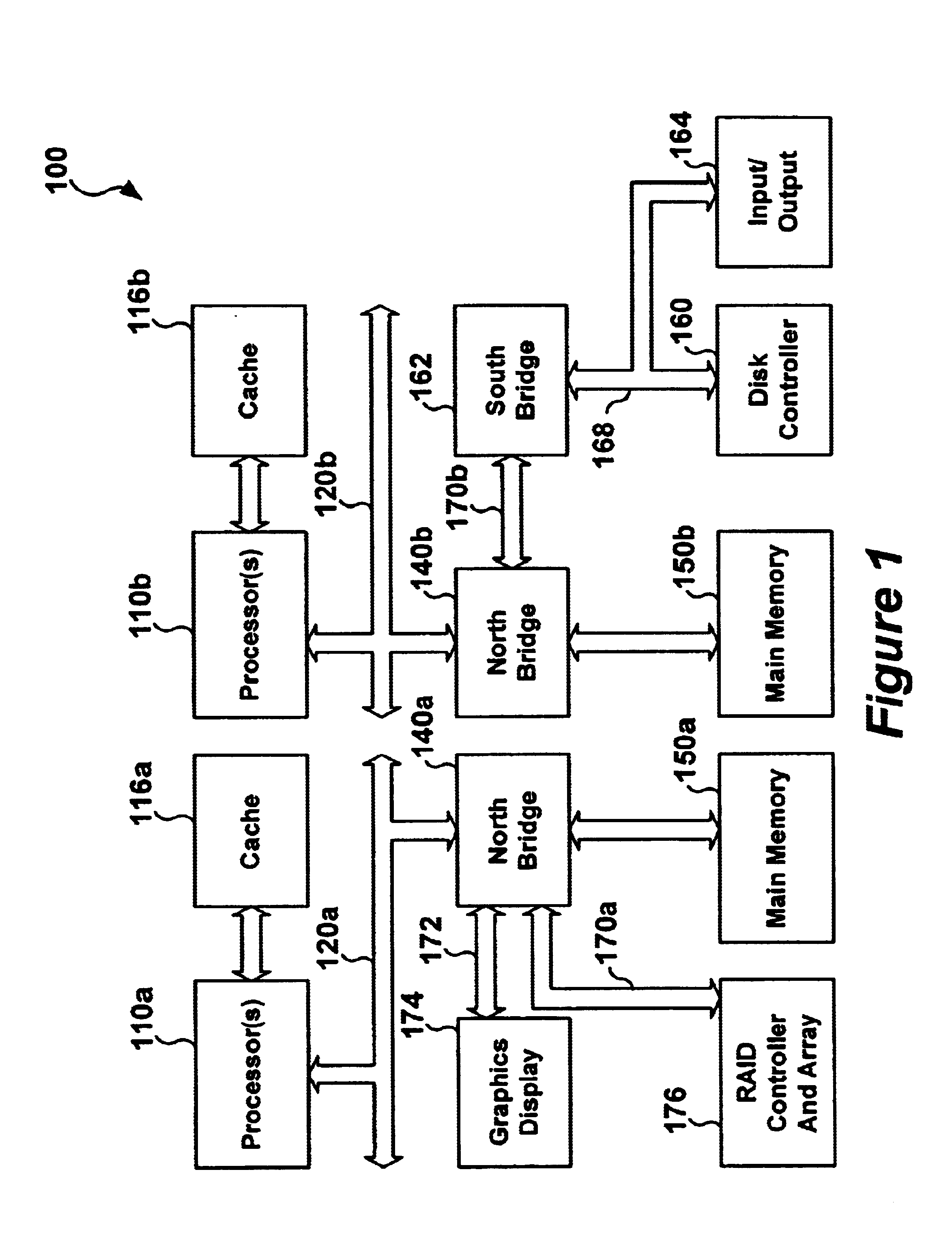
For purposes of this disclosure, an information handling system may include any instrumentality or aggregate of instrumentalities operable to compute, classify, process, transmit, receive, retrieve, originate, switch, store, display, manifest, detect, record, reproduce, handle, or utilize any form of information, intelligence, or data for business, scientific, control, or other purposes. For example, an information handling system may be a personal computer, a network storage device, or any other suitable device and may vary in size, shape, performance, functionality, and price. The information handling system may include random access memory (RAM), one or more processing resources such as a central processing unit (CPU), hardware or software control logic, ROM, and / or other types of nonvolatile memory. Additional components of the information handling system may include one or more disk drives, one or more network ports for communicating with external devices as well as various inp...


PUM


Abstract

A probe for measuring radio frequency/electromagnetic interference (RF/EMI) is used in combination with a spectrum analyzer or oscilloscope (measuring equipment) to measure and/or test for EMI in electronic equipment. The RF/EMI probe has high dielectric transformer isolation between the input of the measuring equipment and the circuit under test so as to prevent damaging the measuring equipment if a high voltage or current is encountered in the circuit being tested. The RF/EMI probe comprises a measurement tip connected to a shielded sense line, the shielded sense line is electro-magnetically coupled to a toroid forming a RF transformer, a high impedance termination load is connected to the shielded sense line, a shielded coaxial cable having a center conductor connected to a secondary winding on the toroid transformer, the shielded coaxial cable being adapted for connection to an input of the measuring equipment. The shield of the coaxial cable is continuous between the input connector of the measuring equipment and a shielded enclosure surrounding the toroid transformer. The coaxial cable may terminate in a RF connector, e.g., BNC and the like, for quick connection to and disconnection from the measuring equipment.

Description

BACKGROUND OF THE INVENTION TECHNOLOGY1. Field of the InventionThe present invention is related to electromagnetic radio frequency testing of electronic circuits, and more specifically, to the measurement and testing of radio frequency and electromagnetic interference (EMI) signals in electronic equipment without substantially loading the circuit being measured.2. Description of the Related ArtAs the value and use of information continues to increase, individuals and businesses seek additional ways to process and store information. One option available to users is information handling systems. An information handling system generally processes, compiles, stores, and / or communicates information or data for business, personal, or other purposes, thereby allowing users to take advantage of the value of the information. Because technology and information handling needs and requirements vary between different users or applications, information handling systems may also vary regarding wha...

Claims


Application Information

Patent Timeline
IPC IPC(8): G01R1/067
CPCG01R1/06788G01R1/06772
Inventor TANNEHILL, JOSEPH W.
Owner DELL PROD LP
Why Eureka
Try Eureka