Partition system

a technology of partition system and connector, which is applied in the direction of service system furniture, walls, transportation and packaging, etc., can solve the problems of difficult use, difficult positioning in the desired location, and relatively heavy elongated connector members

Inactive Publication Date: 2007-05-01
LIFETIME PRODUCTS
View PDF89 Cites 47 Cited by
  • Summary
  • Abstract
  • Description
  • Claims
  • Application Information

AI Technical Summary

Benefits of technology

[0016]Another aspect is a partition system that may include one or more components and the components are preferably interchangeable. Significantly, this may allow the partition system to be rapidly assembled and easily changed. This may also allow the partition system to create structures that are temporary or permanent. Significantly, these structures can be freestanding and independent from other structures, or the structures can be attached or secured to one or more other structures. In addition, while a frame may be used to connect and / or assembly the partition system, a frame is not required.
[0032]Another aspect is a partition system that may include one or more panels or partitions. One or more of the panels may include one or more reinforcing members, which may be used to strengthen and / or increase the rigidity of the panels. In addition, the reinforcing members may provide additional structural integrity for one or more portions of the panel. The panels may also include two or more reinforcing members if desired. While the reinforcing members may be located proximate at least a portion of an edge of a panel, the reinforcing members may be located in any desired portion of the panel.

Problems solved by technology

Disadvantageously, these conventional I-beam type connector members are often elongated members that are difficult to attach to the panels.
These elongated connector members are also relatively heavy, difficult to use and difficult to position in the desired locations.
These connectors, however, often include a number of parts and are complicated to use.
In addition, many conventional connectors are constructed from metal, which is heavy and may include sharp edges.
These metal connectors, which are typically exposed to the elements, may rust, deteriorate or otherwise weaken over time.
Further, these metal components are often bent, twisted, or otherwise deformed from the desired configuration.
Disadvantageously, these panels are often heavy, difficult to move and ship, expensive to manufacture, and the panels generally require finishing such as sanding and / or painting.
The plastic panels, however, are often not sufficiently rigid and the panels often create a flimsy structure because the panels do not have adequate structural integrity.
The plastic panels may also be difficult to securely interconnect and the plastic panels may buckle or crack.
Disadvantageously, the opposing sides of conventional plastic panels may be different.
Thus, the panels are not truly interchangeable because the sides of the panels must be arranged in a particular relationship.
Significantly, the different opposing sides of the panels may limit the usefulness of the panels.
Accordingly, because conventional panels constructed from plastic often include opposing sides that have different configurations, the usefulness of the panels may be limited.
In addition, one or more sides of conventional plastic panels often include imperfections or other types of visual defects that are created during the manufacturing process.
This may also limit the usefulness of the panels.
Conventional panels constructed from blow-molded plastic, however, are typically not high-strength components because, for example, of the hollow interior space.
In fact, conventional blow-molded panels are often relatively low-strength, which may allow the panels to buckle or fail.
Disadvantageously, the thicker outer walls of the ribs require additional plastic materials be used to create the structure, which increases costs and weight.
This undesirably increases the time of the manufacturing process because blow-molded structures cannot be removed from the mold until the structures are sufficiently cooled.
Thus, the opposing surfaces of conventional blow-molded structures may be uneven because different portions of the structures are supported differently.

Method used


Image

  • Partition system
  • Partition system
  • Partition system

Examples


Embodiment Construction

[0062]The present invention is directed towards a partition system. The principles of the present invention, however, are not limited to a partition system. It will be understood that, in light of the present disclosure, the partition system disclosed herein can be successfully used in connection with other types of systems, devices, structures and the like.

[0063]Additionally, to assist in the description of the partition system, words such as top, bottom, front, rear, right and left are used to describe the accompanying figures. It will be appreciated, however, that the partition system can be located in a variety of desired positions—including various angles, sideways and even upside down. A detailed description of the partition system now follows.

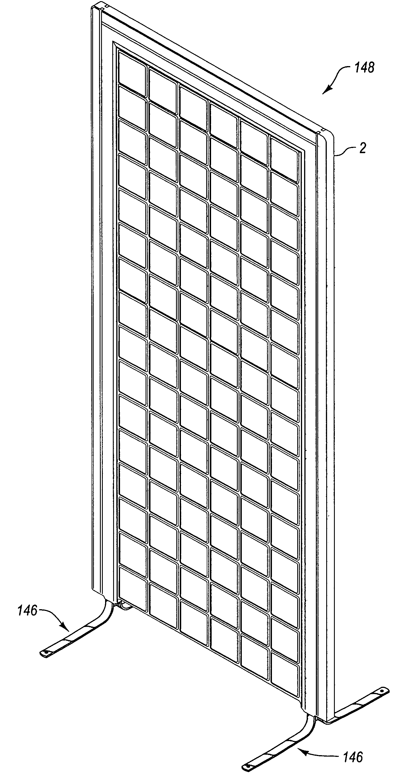
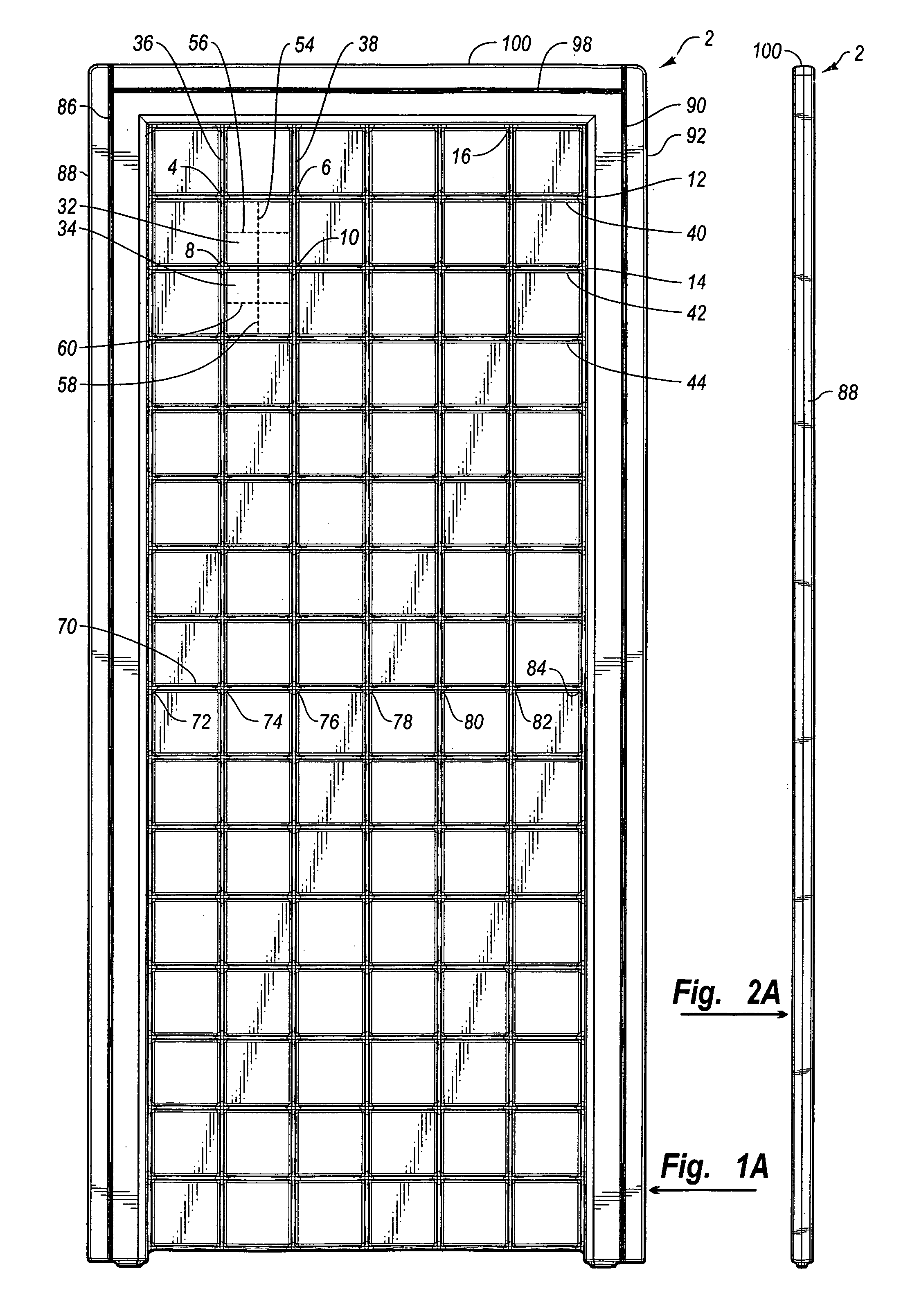
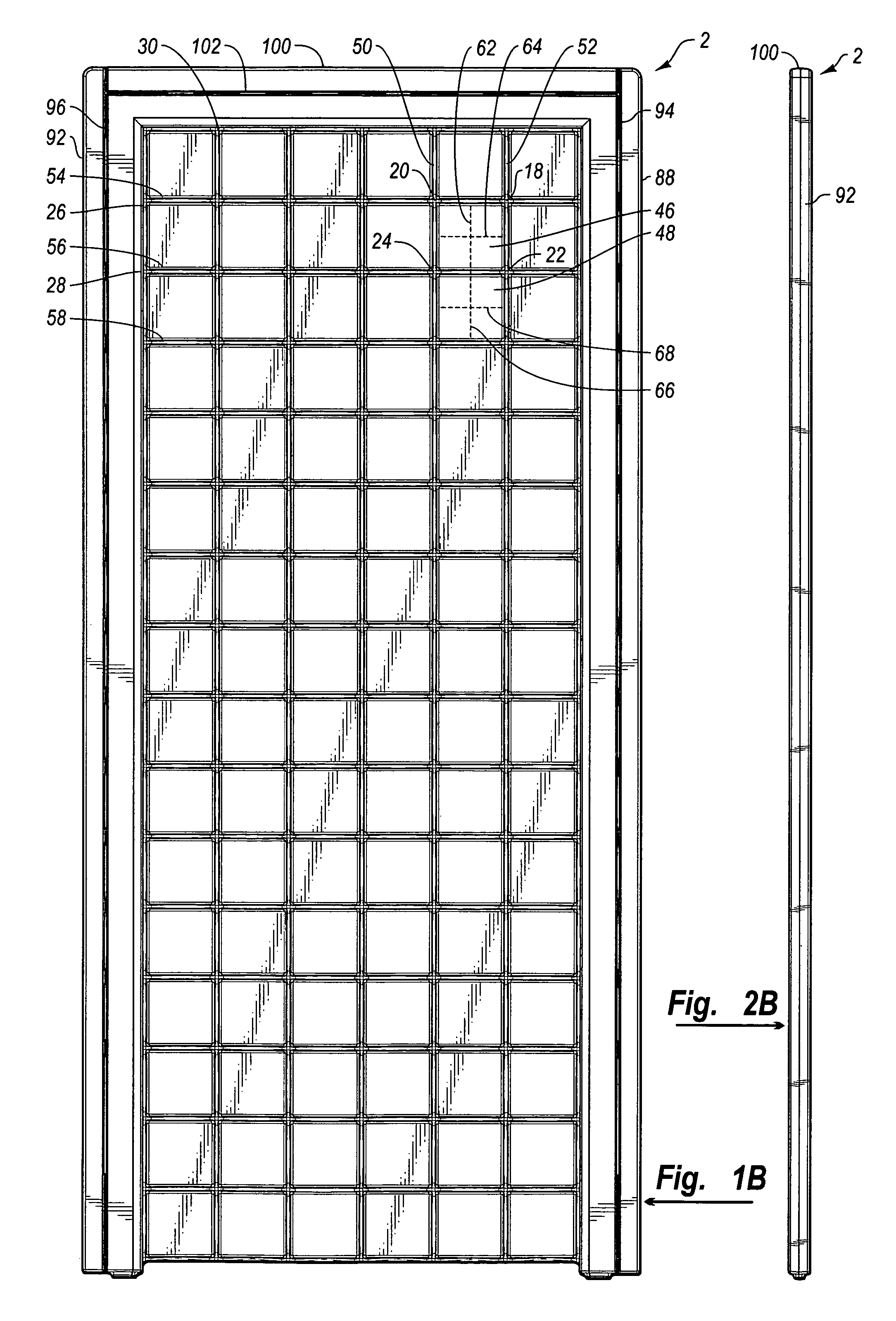
[0064]As shown FIG. 1A, the partition system may include one or more panels or partitions 2, such as shown in the accompanying figures. As discussed in greater detail below, one or more of the panels 2 may be used to create a variety of ...


PUM

PropertyMeasurementUnit
widthaaaaaaaaaa
heightaaaaaaaaaa
structureaaaaaaaaaa

Abstract

A partition system may include one or more panels. A panel may be constructed using blow-molded plastic. A panel may include one or more depressions, which may be aligned with one or more depressions on an opposing side of the panel. The depressions may provide additional structural integrity for a panel. The depressions on opposing sides of the panel may extend toward and engage each other. The panels may include patterns with which one or more depressions may intersect. The panels may include symmetric patterns on opposing sides. The partition system may include one or more connectors adapted to receive a portion of one or more panels. The partition system may include one or more feet that may be attached to one or more panels. The panels may include one or more reinforcing members of various shapes disposed proximate one or more edges of a panel.

Description

CROSS-REFERENCE TO RELATED APPLICATIONS[0001]This application claims priority to and the benefit of U.S. Provisional Patent Application Ser. No. 60 / 487,748, entitled PARTITION SYSTEM, which was filed on Jul. 15, 2003, and this application is a continuation-in-part of U.S. Design patent application Ser. No. 29 / 180,861, entitled PARTITION CONSTRUCTED FROM BLOW-MOLDED PLASTIC, which was filed on Apr. 30, 2003 now U.S. Pat. No. D500,604; a continuation-in-part of U.S. Design patent application Ser. No. 29 / 180,870, entitled CLIP FOR CONNECTING ONE OR MORE PARTITIONS, which was filed on Apr. 30, 2003 now abandoned; and a continuation-in-part of U.S. Design patent application Ser. No. 29 / 186,355, entitled SUPPORT FOR A PARTITION, which was filed on Jul. 14, 2003 now abandoned. Each of these applications is hereby incorporated by reference in their entireties.BACKGROUND OF THE INVENTION[0002]1. Field of the Invention[0003]The present invention generally relates to a partition system and, in...

Claims


Application Information

Patent Timeline
Patent Type & Authority Patents(United States)
IPC IPC(8): E04C2/00E04BE04B2/74E04H1/00
CPCE04B2/7422E04C2/20Y10T428/1352
Inventor STEED, BRENTCALKIN, JAYASHBY, KENT
Owner LIFETIME PRODUCTS
Why Eureka
Try Eureka