
Outboard engine

a technology for outboard engines and drive shafts, which is applied in the direction of marine propulsion, propulsion transmission, vessel construction, etc., can solve the problems of complex attachment structure of the cover and the drive shaft housing, increased number of steps for attachment, and inferior operability, so as to reduce the number of components, improve the appearance, and improve the appearan

Inactive Publication Date: 2007-05-01
HONDA MOTOR CO LTD
View PDF3 Cites 1 Cited by
  • Summary
  • Abstract
  • Description
  • Claims
  • Application Information

AI Technical Summary

Benefits of technology

The present invention provides an outboard engine that can be easily attached to a boat and has an improved appearance. The engine is housed in a main body composed of a leg case and a cover that is formed integrally without any dividing or joining lines. The cover is made of a single member and has anti-splash plate on its front surface. The cover also has fastening parts that reinforce its rigidity and can be easily attached to the leg case. The cover can be separately attached from the attachment device and has a limited height to prevent unnecessary increase in its width. The technical effects of the invention are improved appearance, simplified attachment process, reduced number of components, and reinforced rigidity.

Problems solved by technology

However, since this cover is configured from two members, which are the port cover and the starboard cover, a large number of attachment bosses is needed to attach and support these two members on the outer surface of the drive shaft housing, the attachment structure of the cover and the drive shaft housing is complicated, and the number of steps for attachment is increased.
Particularly, since the cover is configured from two members, pressure must be applied to both the left and right components when the left and right components are assembled, making operability inferior.

Method used


Image

  • Outboard engine
  • Outboard engine
  • Outboard engine

Examples


Embodiment Construction

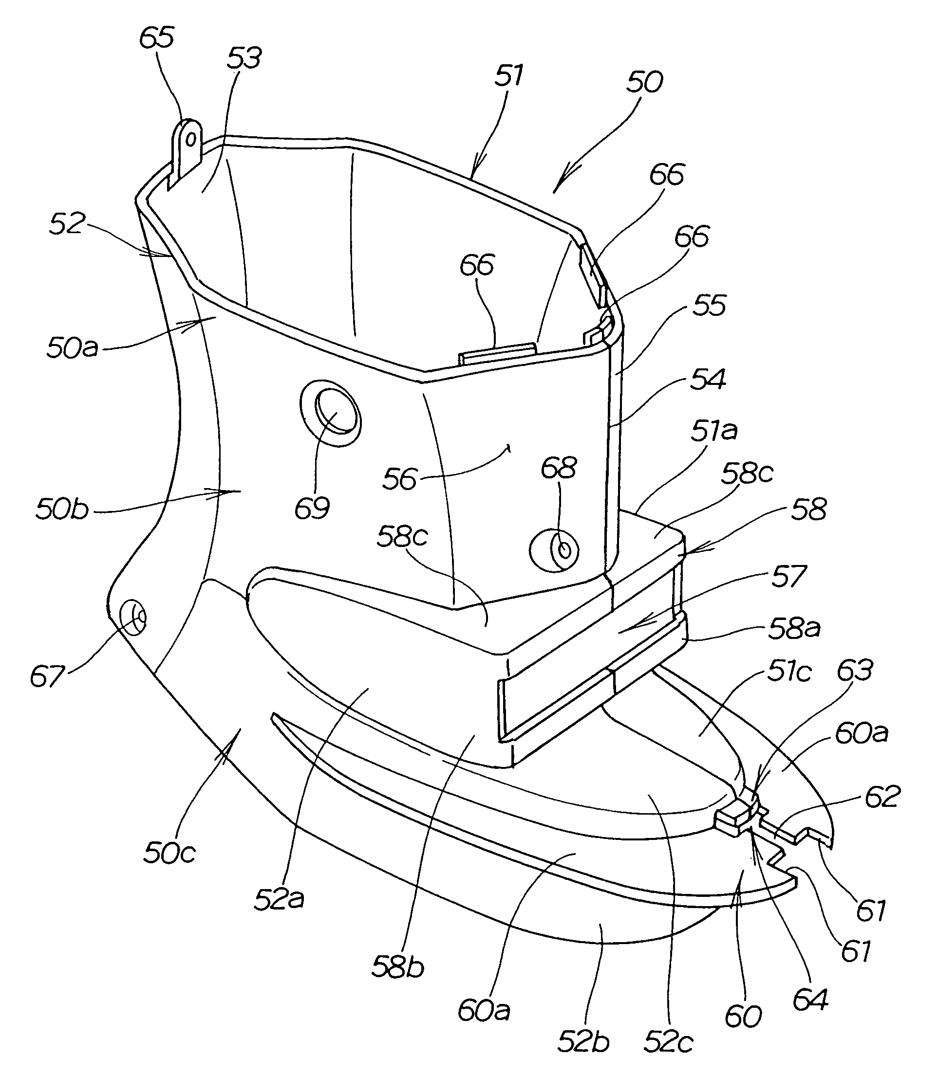
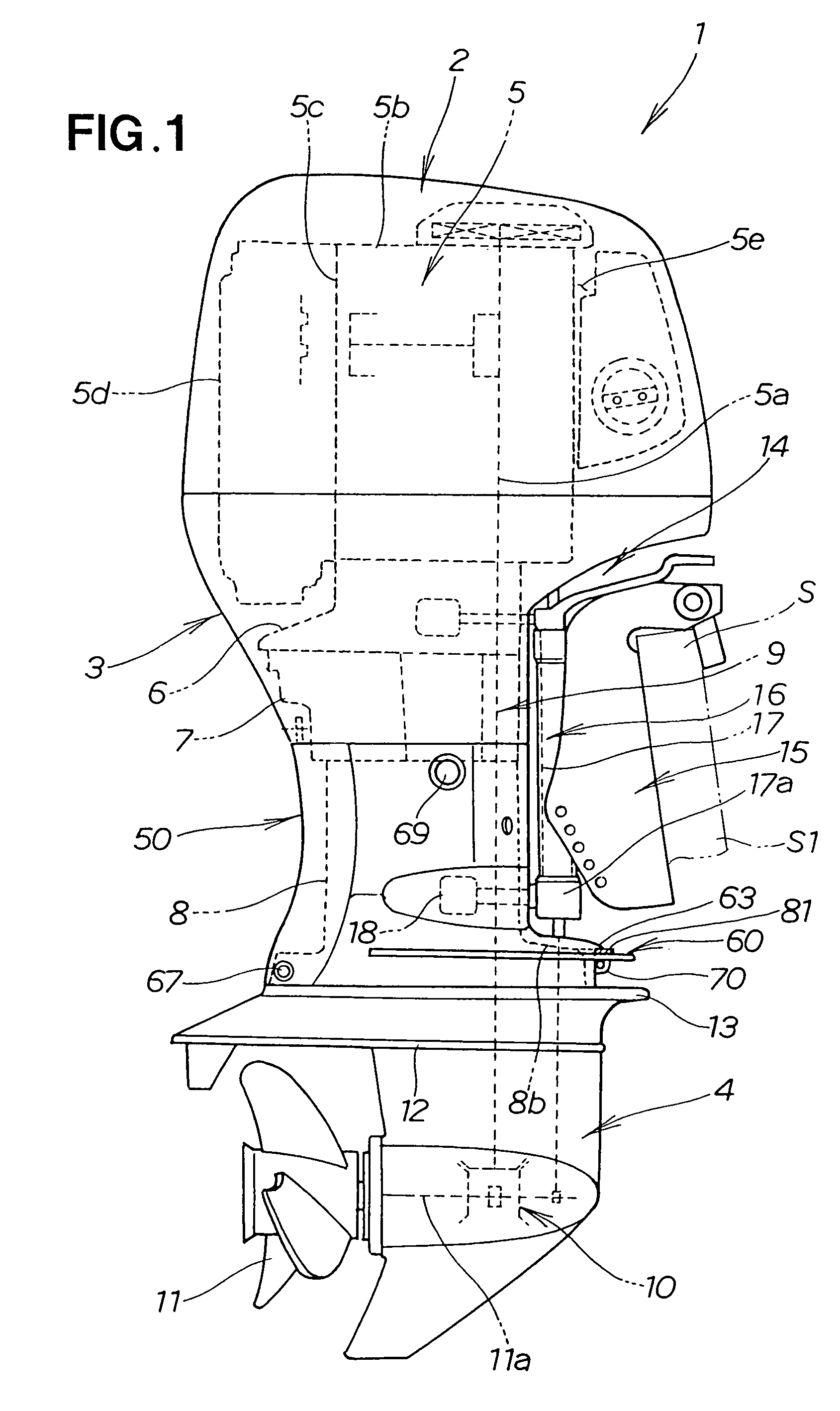
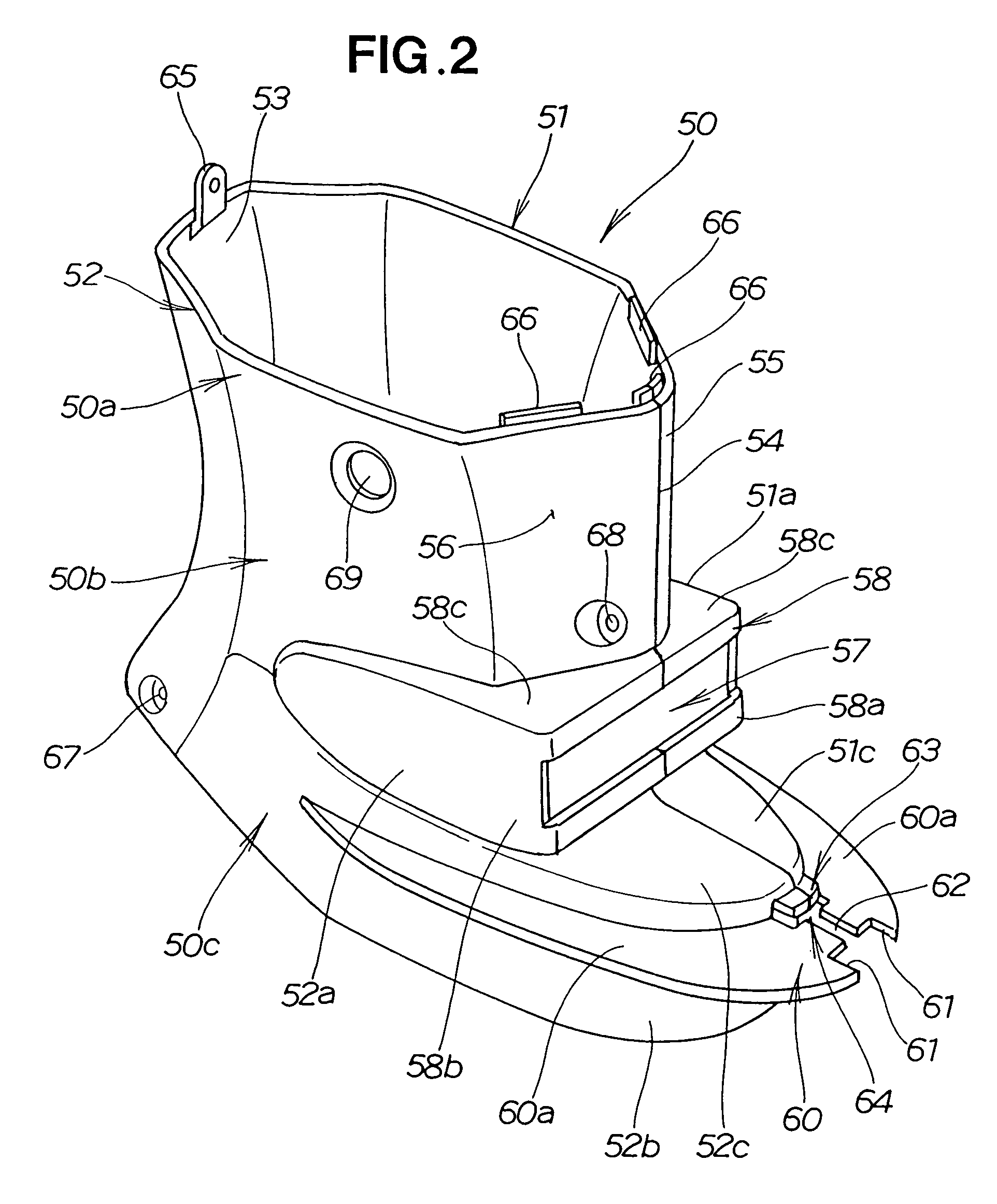
[0024]Referring to FIG. 1, an outboard engine 1 comprises an engine cover 2 that houses an engine part 5; an undercover 3 that is positioned below the engine cover 2; a leg cover 50 that is positioned below the undercover 3 and that covers a leg case (extension case) 8, which is a drive shaft housing; and a gear case 4 at the lowest position.

[0025]The engine part 5 is composed of a multi-cylinder four-stroke engine having a longitudinally oriented crankshaft 5a, a transversely oriented cylinder block 5b, a cylinder head 5c, a cylinder head cover 5d, a crankcase 5e, and a camshaft (not shown).

[0026]The engine cover 2 covers the top half of the engine part 5, and the top of the undercover 3 covers the bottom of the engine part 5. The bottom end of the engine part 5 is supported by a mounting case 6. An oil case 7 is disposed below the mounting case 6. The oil case 7 and the gear case 4 are connected by the leg case 8.

[0027]A drive shaft 9 is connected to the crankshaft 5a, and passes ...


PUM


Abstract

An outboard engine with a cover for allowing for an improved outward appearance is disclosed. The engine includes a leg case that houses a drive shaft for transmitting the output from the engine to a propeller. The cover covers the leg case. The cover is formed integrally, and a front part is designed to be opened. The front part is opened and is made to encase and cover a periphery of the leg case.

Description

FIELD OF THE INVENTION[0001]The present invention relates to an outboard engine that is steerably attached to the hull of a boat.BACKGROUND OF THE INVENTION[0002]Japanese Patent Laid-Open Publication No. 7-149289 (JP-A-7-149289) discloses an outboard engine wherein the outer surface of a drive shaft housing (extension case) in the vertical middle of the outboard engine is covered by a cover.[0003]In this outboard engine, the outer surface of the drive shaft housing is covered with a cover made of a synthetic resin to reduce the finishing costs needed to improve the outward appearance of the drive shaft housing, and also to simplify the design of the drive shaft housing.[0004]The cover that covers the outer surface of the drive shaft housing is configured from a two-piece dividable cover having a port cover and a starboard cover.[0005]Thus, in this outboard engine, covering the outer surface of the drive shaft housing with a cover made of a synthetic resin makes it possible to improv...

Claims


Application Information

Patent Timeline
Patent Type & Authority Patents(United States)
IPC IPC(8): B63H23/00
CPCB63H20/32
Inventor KITSU, KUNIHIRORINZAKI, SHOICHI
Owner HONDA MOTOR CO LTD
Learn More