Methods for manufacturing a clip and clip

a manufacturing method and clip technology, applied in the field of methods for manufacturing a clip and a clip, can solve the problems of limited minimizing of conventional manufacturing methods, and achieve the effect of reducing the size of the clip's footprint and enhancing the sealing function of the clip

Inactive Publication Date: 2007-05-01
INTEGRATED VASCULAR SYST
View PDF6 Cites 190 Cited by
  • Summary
  • Abstract
  • Description
  • Claims
  • Application Information

AI Technical Summary

Benefits of technology

[0003]The present invention is directed to methods for manufacturing tissue engaging clips in a manner in which a clip-precursor is first formed and such precursor is then reconfigured into the final shape of the clip. In a preferred embodiment of the invention, a clip having an annular or hoop-shaped generally planar configuration with radially inwardly extending tines is manufactured by first forming a precursor with the tines extending radially outward and then reconfigured by inserting the precursor to its final shape with the tines extending radially inward and then heat setting the clip in this configuration. This permits the tines to be packed more closely together which enhances the sealing function of the clip and reduces the size of the clip's footprint. As will be explained in more detail herein, this manufacturing method overcomes the limitations of conventional methods in which the clip is manufactured in its final configuration.

Problems solved by technology

Conventional manufacturing methods are limited with regard to minimizing the space between the tines because the necessary manufacturing tolerances require that sufficient space be allowed for the manufacturing tools and / or processing materials.

Method used


Image

  • Methods for manufacturing a clip and clip
  • Methods for manufacturing a clip and clip
  • Methods for manufacturing a clip and clip

Examples


Embodiment Construction

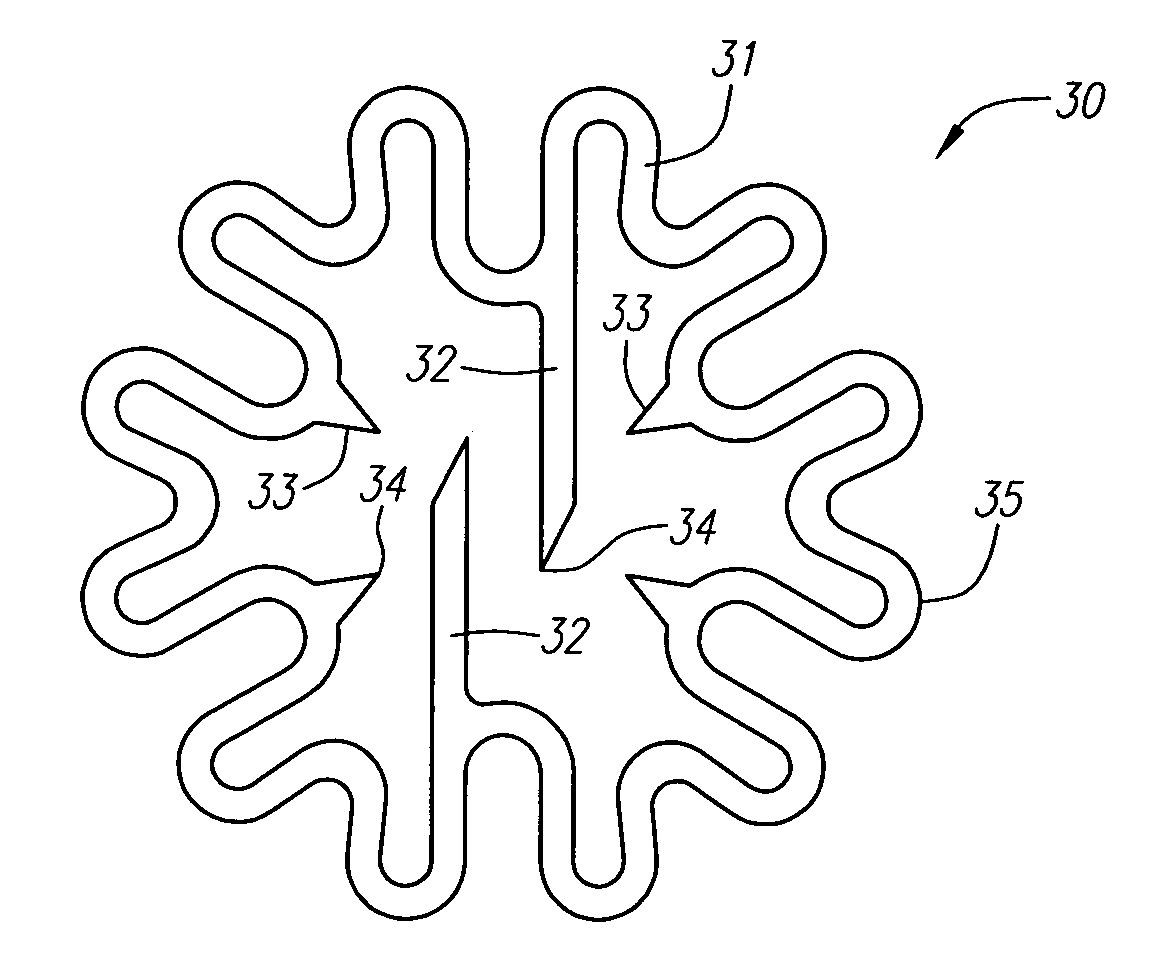
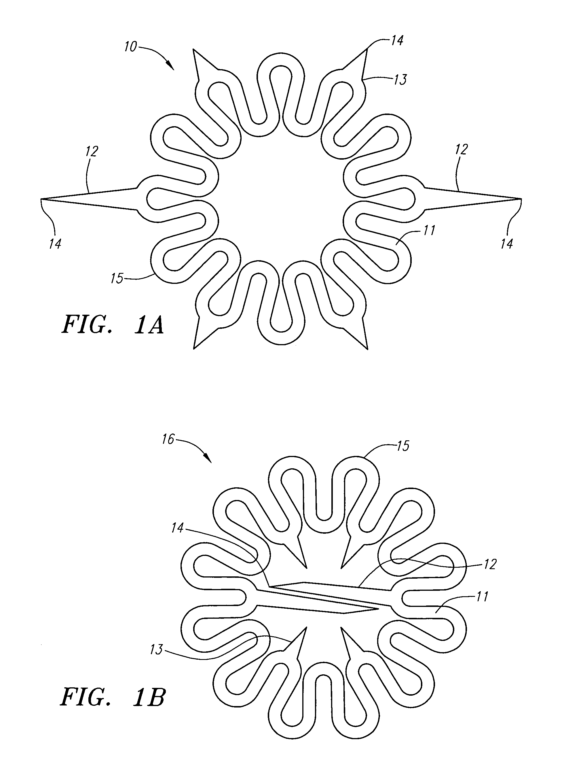
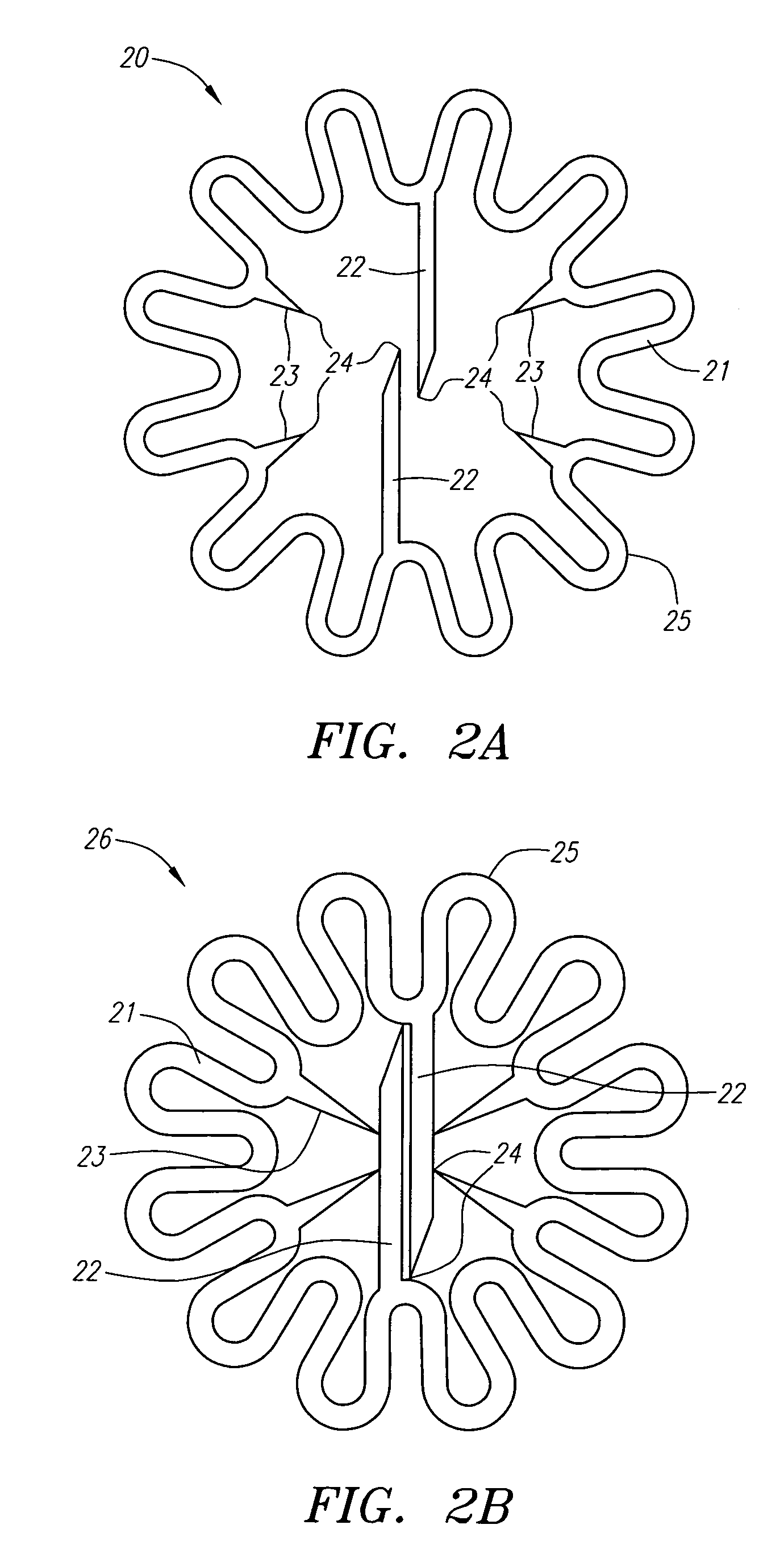
[0011]The clips manufactured according to the present invention are useful for engaging tissue so as to connect tissue segments together or to close and / or seal openings through tissue such as a puncture wound in a body lumen. These clips may be used by deforming them from their generally planar configuration such that the tines are pointing in a direction generally transverse to the plane, holding the clip in this deformed condition, deploying the clip proximal to the tissue to be engaged and removing the deforming force such that the clip engages the tissue and attempts to return to its original generally planar configuration. The methods and apparatus disclosed in the above-mentioned U.S. patent application Ser. Nos. 10 / 081,726 and 09 / 732,178 can be used to deploy the clips of the present invention to engage tissue and close or seal an opening.

[0012]In such use, the deformation of the clip causes the tines to be directed generally axially away from the body of the clip and it is ...


PUM

PropertyMeasurementUnit
lengthaaaaaaaaaa
lengthaaaaaaaaaa
temperatureaaaaaaaaaa

Abstract

The present invention relates to a method of making clips which can be used to engage body tissue for the purpose of closing wounds. Such clips are generally annular in shape and have radially inwardly extending tines. It is often desirable for such clips to have a small lateral dimension, but manufacturing difficulty has been encountered in making small clips because of the difficulty in cutting materials accurately when attempting to produce a clip with closely packed elements. The present invention avoids these difficulties by first forming a precursor which, in one embodiment, has the tines extending radially outwardly from the annular body and then forms the clip by inverting the precursor such that the tines extend radially inwardly. In an alternate embodiment, the precursor is formed with an over-sized lateral dimension and then compressed inwardly to bring the tines closer together and to reduce the lateral dimension of the precursor. It is preferred to manufacture such clips from a superelastic alloy such as nickel-titanium, in which case the inverted or compressed precursor must be heated and quenched to heat set the clip in its final shape.

Description

RELATED APPLICATIONS[0001]This application is a continuation-in-part of U.S. patent application Ser. No. 10 / 081,726, filed Feb. 21, 2002 now U.S. Pat. No. 6,623,510 and is a continuation-in-part of U.S. patent application Ser. No. 09 / 732,178, filed Dec. 7, 2000 now U.S. Pat. No. 6,719,777, the disclosures of each of which are incorporated by reference herein.FIELD OF INVENTION[0002]The use of certain types of clips, which are initially generally planar and which are deformed to non-planar configuration prior to use, to close openings through tissue, e.g., into body lumens, and more particularly to close a puncture made to gain access to a blood vessel or other body lumen is known. Such clips are generally annular and have tines extending radially from an annular body. For example, such clips are disclosed in the aforementioned co-pending applications and in published PCT Applications WO / 99 / 62408, WO / 00 / 56223 and WO / 00 / 56227, the disclosures of which are incorporated by reference her...

Claims


Application Information

Patent Timeline
Patent Type & Authority Patents(United States)
IPC IPC(8): A61B17/08A61B17/00A61B17/064A61B17/068A61B19/00H03K3/356
CPCA61B17/0057A61B17/064A61B17/068A61B17/083C22F1/00C22F1/10C22F1/16C22C19/007A61B17/0644A61B19/54A61B2017/00004A61B2017/00867A61B90/39
Inventor CARLEY, MICHAEL T.GINN, RICHARD S.
Owner INTEGRATED VASCULAR SYST
Why Eureka
Try Eureka