Jack structure

a jack and jack technology, applied in the direction of electrical apparatus casings/cabinets/drawers, casings/cabinets/drawers, coupling device connections, etc., can solve the problems of jack holes not being inserted with anything else, jacks are likely exposed to danger, and electric shock is caused

Inactive Publication Date: 2007-05-01
JAZZ HIPSTER
View PDF10 Cites 6 Cited by
  • Summary
  • Abstract
  • Description
  • Claims
  • Application Information

AI Technical Summary

Benefits of technology

[0007]It is, therefore, an object of the present invention to provide an improved jack structure in which a lock piece and protective covers are disposed against each other so that the jack holes thereof can be prevented from being inserted with an acute object and thus from occurrence of electric shock.

Problems solved by technology

For a home with a child, the jacks are likely exposed to danger since the child may curiously insert some conductive material into the jack holes.
When this occurs, electric shock would be caused.
As such, the jack holes cannot be inserted with anything else.
However, the child might possibly detach the jack cover, stultifying the safety design of the plastic jack cover and still causing the safety issue to be concerned.

Method used


Image

  • Jack structure
  • Jack structure
  • Jack structure

Examples


Embodiment Construction

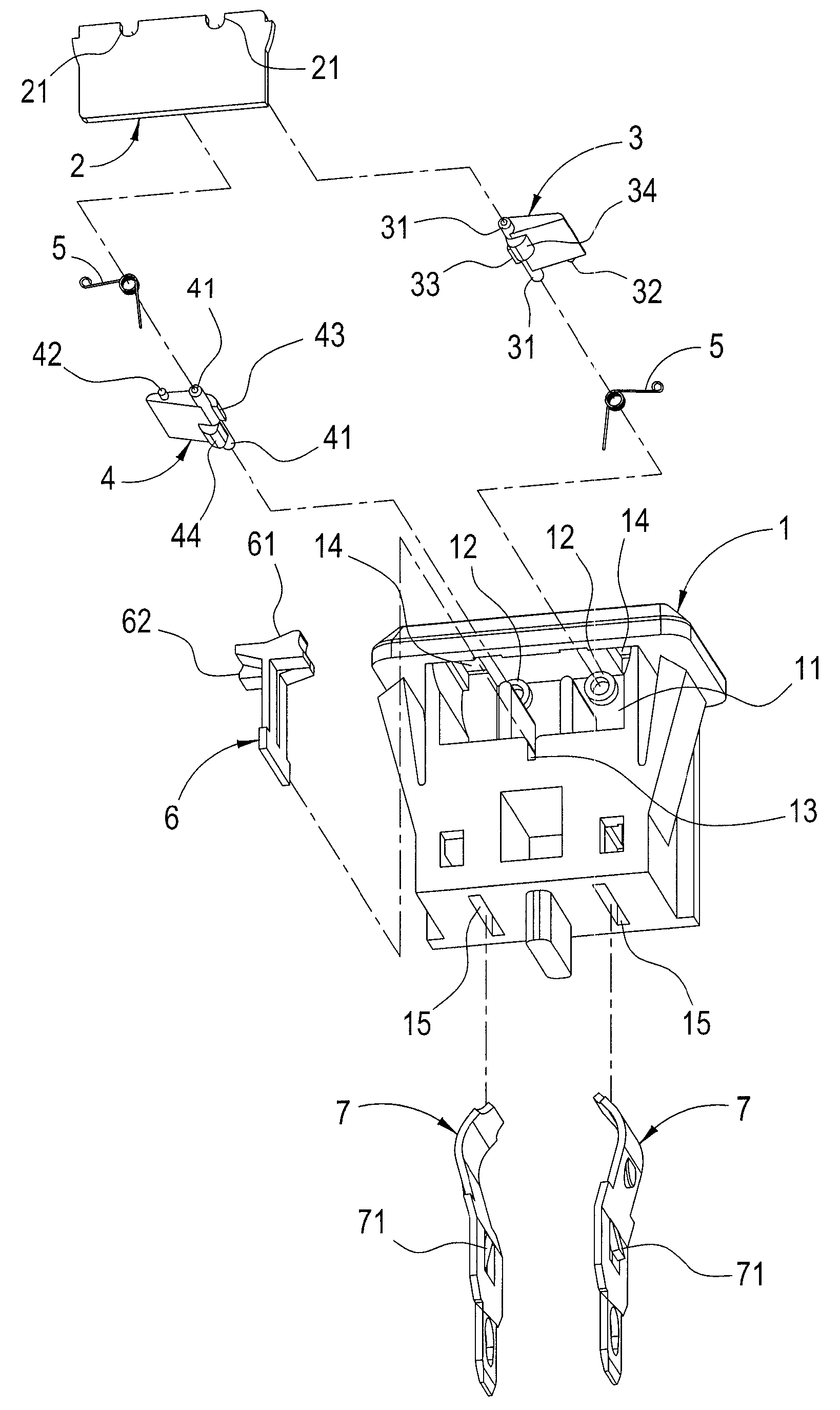
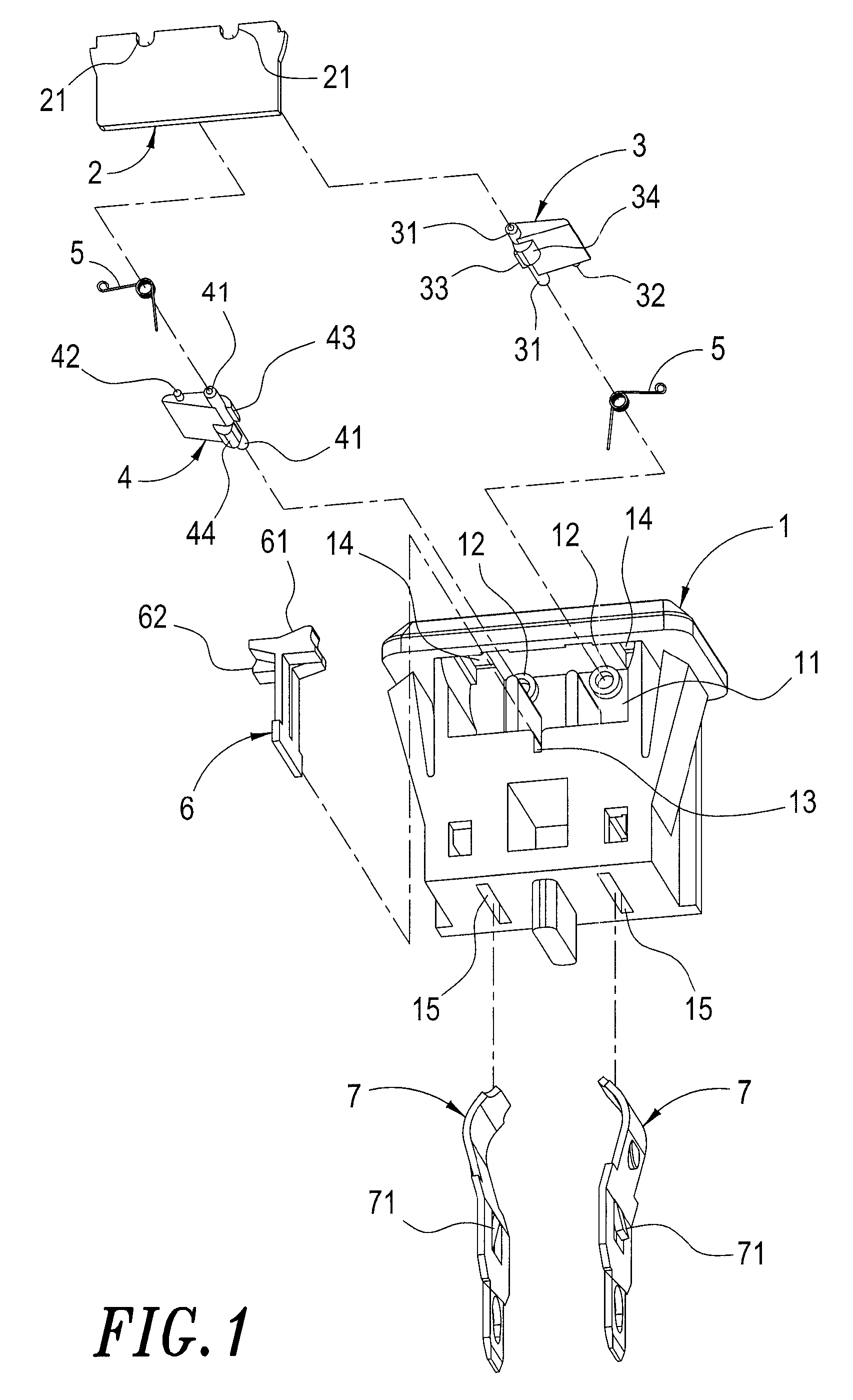
[0015]Referring to FIG. 1 through FIGS. 4A–4C, an improved jack structure according to the present invention is shown therein.

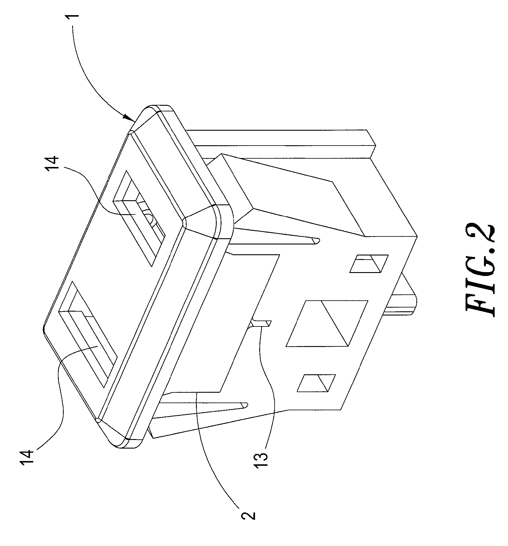
[0016]The jack structure comprises a main body 1, a cover plate 2, two protective covers 3, 4, a lock piece 6 and conductive pieces 7. The main body 1 has a fillister 11 disposed at a center region. Within the fillister 11, two connection axis holes 12 and an insertion slot 13 are disposed. On the main body 1, two jack holes 14 are provided at an upper portion thereof and two insertion holes 15 are provided at a lower portion thereof. The jack holes 14, insertion holes 15 and fillister 111 are open to one another.

[0017]The cover plate 2 has two connection holes 21 disposed at an upper region thereof and is received within the fillister 11 of the main body 1 in such a manner that the connection holes 21 and the connection axis holes 12 are aligned to each other.

[0018]At one of two sides of the protective cover 3, there is a respective rotation axis 31. At one ...


PUM


Abstract

Disclosed is an improved jack structure, includes a main body, a cover, two protective covers, a lock piece and a conductive piece. When an object is inserted into a single one of insertion holes each corresponding to one of the protective covers on the main body, a corresponding one of the protective covers is pushed to move. A protrusion of the pushed protective cover then pushes an urging portion of the lock piece and the urging portion is stopped by the other one of the protective covers. Therefore, the improved jack structure can be prevented from being inserted with an acute object and thus from occurrence of electric shock.

Description

BACKGROUND OF THE INVENTION[0001]1. Field of the Invention[0002]The present invention relates to an improved jack structure, and more particularly to an improved jack structure in which a lock piece and protective covers are disposed for sealing jack holes when an acute metal material is inserted, thus preventing electric shock from occurring accidentally.[0003]2. Description of the Prior Art[0004]In household environment, there are many electrical sockets or jacks for connecting the appliances to power. For a home with a child, the jacks are likely exposed to danger since the child may curiously insert some conductive material into the jack holes. This is a great concern to the parents. When this occurs, electric shock would be caused.[0005]To solve this problem, a plastic jack cover has been in common use. On the plastic jack cover, two columns are provided which can be inserted into the jack holes. As such, the jack holes cannot be inserted with anything else. However, the child ...

Claims


Application Information

Patent Timeline
Patent Type & Authority Patents(United States)
IPC IPC(8): H02G3/14
CPCH01R13/4536
Inventor YANG, LIEN-HUANG
Owner JAZZ HIPSTER
Why Eureka
Try Eureka