Engineered structural members and methods for constructing same

a technology of structural members and flanges, applied in the direction of girders, joists, trusses, etc., can solve the problems of not being able to fit with standard fasteners, joists contain hollow cores with wide flanges, and are sensitive to environmental conditions, so as to improve the load bearing rating of the final product, improve the bonding, and enhance the bonding

Active Publication Date: 2007-05-08
TAC TECH
View PDF179 Cites 39 Cited by
  • Summary
  • Abstract
  • Description
  • Claims
  • Application Information

AI Technical Summary

Benefits of technology

[0011]An illustrative I-joist product in one aspect of the present invention defines a vertical center member preferably including HDPE, and top and bottom flanges interconnected to the vertical center member, also including HDPE. The HDPE provides a relatively hard, durable, substantially weather-resistant structure. The flanges form a system having structural vigor and enable the HDPE-based system to provide sufficient strength, construction flexibility, and true alignment (i.e., true to specification).
[0026]Various embodiments of the present invention may also include joists without outer flanges. Thus, in accordance with embodiments of the present invention, a structural joist is provided comprising a vertical center member, a top flange and a bottom flange connected to the vertical center member, and a reinforcing member substantially embedded within at least one of the top flange and the bottom flange, the reinforcing member extending along substantially an entire length of a longitudinal axis of the at least one of the top flange and the bottom flange, wherein a strength of the structural joist is increased.

Problems solved by technology

Wood-containing products generally are sensitive to environmental conditions, such as the effect of moisture.
These plastic lumber products are typically heavy and contain fiberglass fibers that can quickly dull saw blades and drill bits of construction equipment used to size the materials.
Other known HDPE I-joists contain hollow cores with wide flanges that are not conducive to easy cutting-to-dimension with standard construction tools, nor fit with standard fasteners.

Method used


Image

  • Engineered structural members and methods for constructing same
  • Engineered structural members and methods for constructing same
  • Engineered structural members and methods for constructing same

Examples


Embodiment Construction

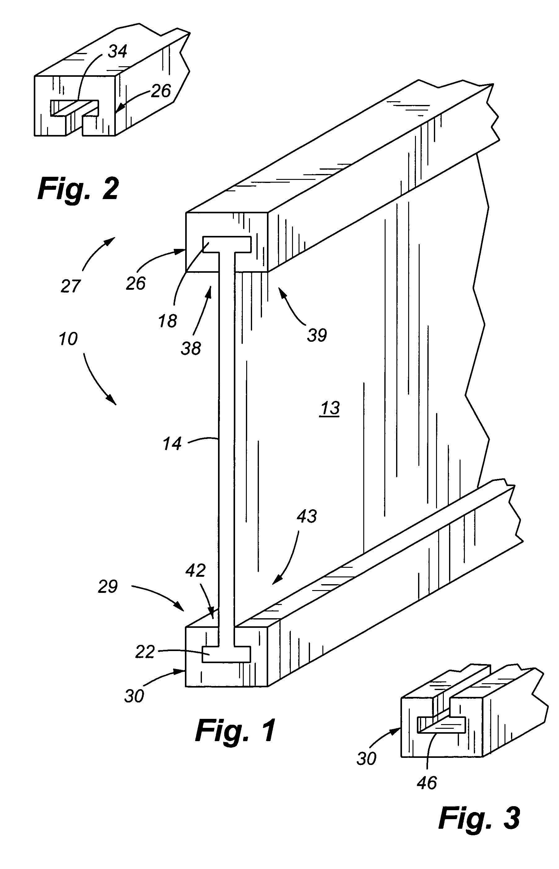
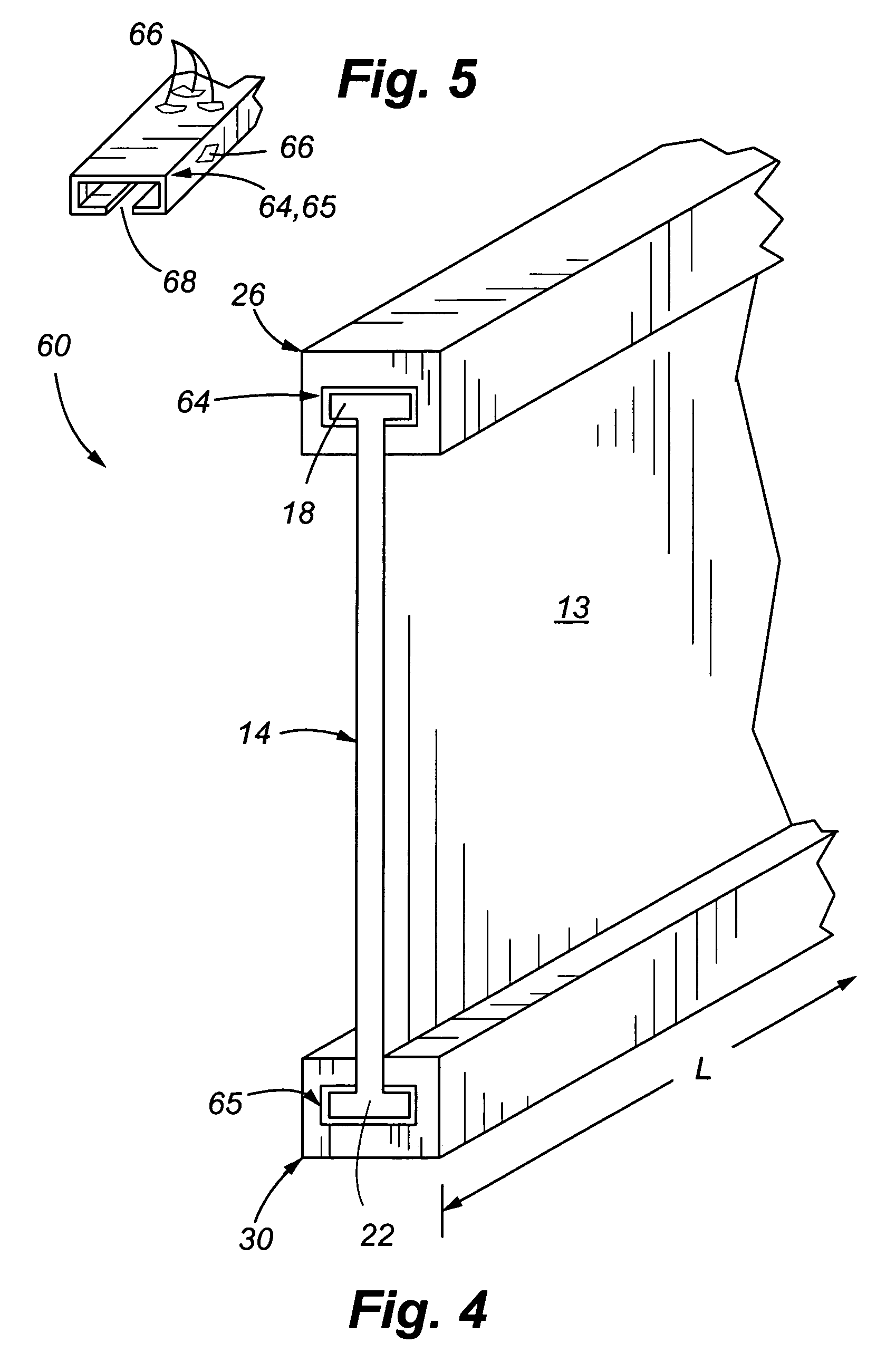
[0053]Referring now to FIG. 1, in accordance with embodiments of the present invention, an illustrative I-joist structural member 10 is shown. I-joist 10 includes a web member 13. Web member 13 has a central web or webbing 14, an upper flange 18, and a lower flange 22, wherein flanges 18, 22 are interconnected by webbing 14.

[0054]As part of a typical I-joist, webbing 14 interacts as a load-bearing member with load-bearing upper and lower flanges 18, 22. In one embodiment, web member 13 includes webbing 14, upper flange 18 and lower flange 22 formed of a relatively hard, durable, flexible, and substantially weather-proof material, including but not limited to thermoplastics, such as HDPE, and / or thermoplastic composite materials, such as HDPE with additives such as, for example, natural or man-made fibers or particles of various materials / compositions, including but not limited to wood particles and / or fiberglass strands. Preferably web member 13 is extruded.

[0055]I-joist 10 also inc...


PUM

PropertyMeasurementUnit
foot lengthsaaaaaaaaaa
longitudinal lengthaaaaaaaaaa

Abstract

A system and method of manufacture providing reinforced structurally functional load-bearing members, including but not limited to using thermoplastic materials, such as High Density Polyethylene (HDPE), reinforced such as with an aluminum alloy or carbon fiber core element. Among its possible uses, the present invention has application for provision of structural support members, such as an illustrative I-joist product having a vertical center member preferably comprising HDPE, and top and bottom flanges having structurally meaningful reinforcement. The center member and flanges preferably comprising HDPE provides a relatively hard, durable, substantially weather-resistant structure.

Description

CROSS REFERENCE TO RELATED APPLICATION[0001]The present application claims the benefit of U.S. Provisional Application No. 60 / 598,014 filed on Aug. 2, 2004, U.S. Provisional Application No. 60 / 644,451 filed on Jan. 14, 2005, and U.S. Provisional Application No. 60 / 686,870 filed on Jun. 1, 2005, the entire disclosures of which are incorporated herein by reference in their entirety.FIELD OF THE INVENTION[0002]The present invention is directed to construction materials, and more particularly, to structural members, such as joists, posts and beams, as well as methods of manufacturing the same.BACKGROUND OF THE INVENTION[0003]Use of engineered materials, such as wood composites and various plastics, including recyclable thermoplastic, such as high-density polyethylene (HDPE), is becoming increasingly popular in the construction industry. These uses encompass various horizontal and vertical applications that meet a range of present decorative and / or structural construction needs.[0004]Str...

Claims


Application Information

Patent Timeline
Patent Type & Authority Patents(United States)
IPC IPC(8): E04C3/30
CPCE04C3/29E04C3/30Y10T29/49616E04C2003/0413E04C2003/043E04C2003/0434E04C2003/0439E04C2003/0447E04C2003/0452E04C2003/0465E04C2003/0469E04C2003/0478Y10T29/49623Y10T29/49982Y10T29/49625
Inventor CARLSON, BARRYUNDERHILL, JASON
Owner TAC TECH
Why Eureka
Try Eureka