Offset mold process

a mold and offset technology, applied in the field of casting molten metal, can solve the problems of limiting the application of this technique, requiring scrapping of the entire casting, and causing casting defects

Inactive Publication Date: 2007-05-08
EVANS DWIGHT +2
View PDF6 Cites 8 Cited by
  • Summary
  • Abstract
  • Description
  • Claims
  • Application Information

AI Technical Summary

Benefits of technology

[0001]The present invention is directed to the field of casting molten metal. More particularly, the present invention is directed to a process for

Problems solved by technology

Such a technique can result in creation of eddy currents which produce defects in the casting.
If the defect goes beneath the surface, or if the article is a precision casting, such eddy currents can require scrapping of the entire casting.
The use of vacuum with seals and clamps limits the appli

Method used


Image

  • Offset mold process
  • Offset mold process
  • Offset mold process

Examples


first embodiment

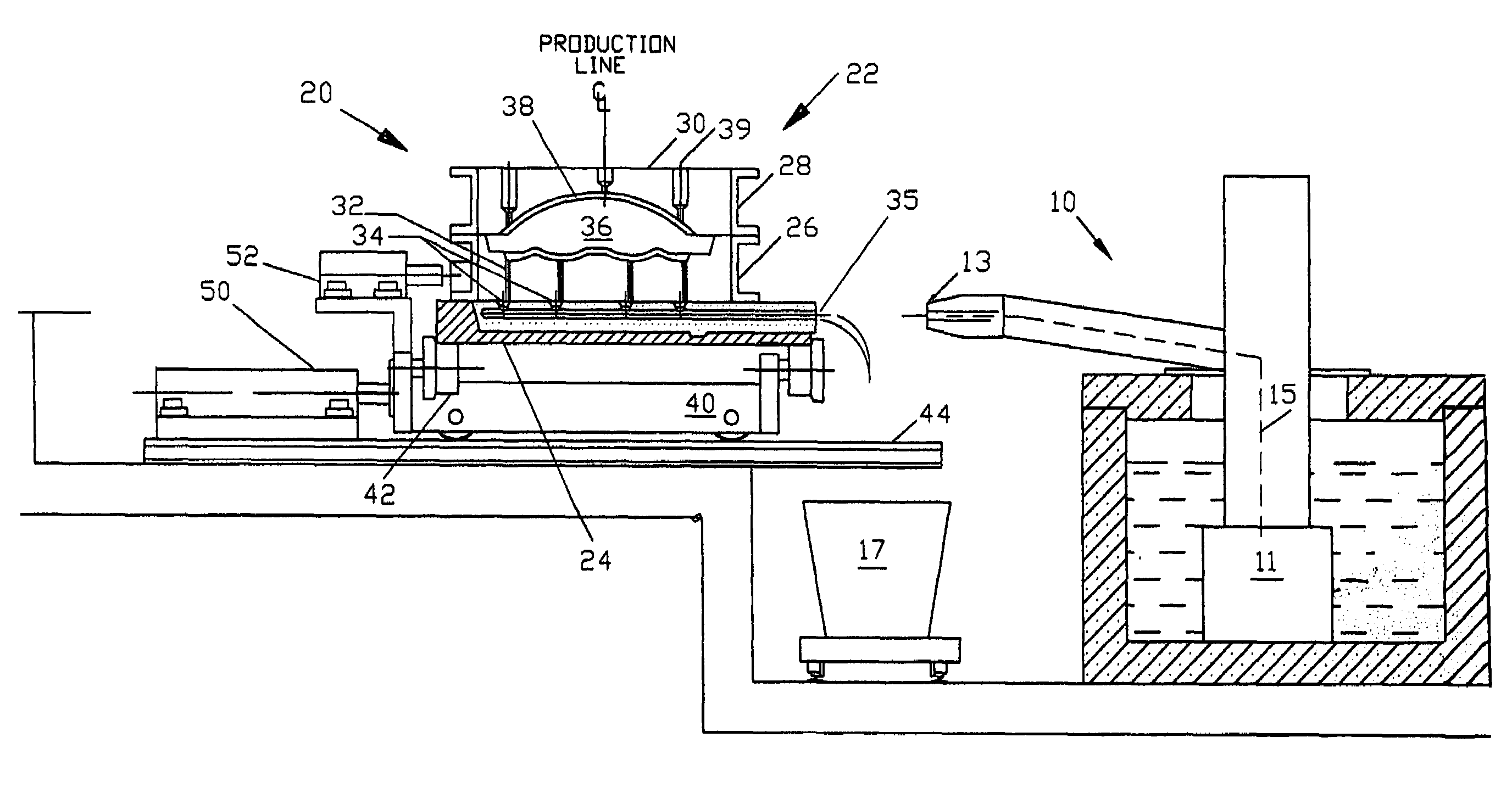
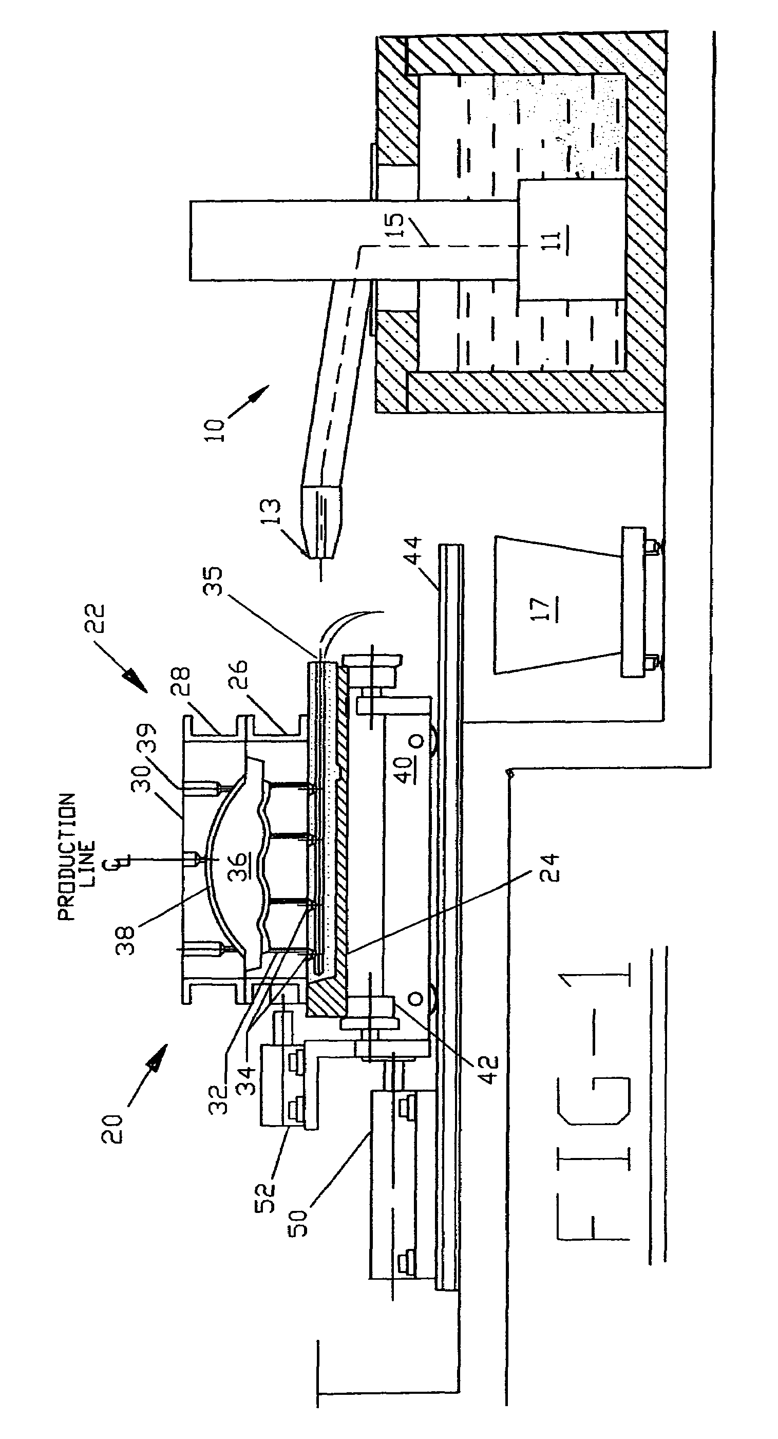
[0013]molding apparatus useful in the offset molding method of the present invention is shown in FIG. 1 generally at 20. In the present method, a mold assembly 22 comprised of a mold bottom board 24, a first mold component, in this case, a drag 26 sitting atop the bottom board 24, with a second mold component, in this case cope 28 sitting atop and pinned to drag 26. It is noted that when drag 26 is originally placed on bottom board 24, it, too, was pinned in place. These pins ensure proper alignment of components as the during the construction of the mold, typically from green sand. However, after the formation of the mold assembly 22 is completed, the pins between the drag 26 and bottom board 24 are removed to permit relative movement there between.

[0014]As seen in FIG. 1, a separate replaceable sand mold 31 positioned in the bottom board 24 will typically be provided with a horizontal runner 34 with entrance port 35. Primary sand mold 30, also made of green sand, is formed with a ...

third embodiment

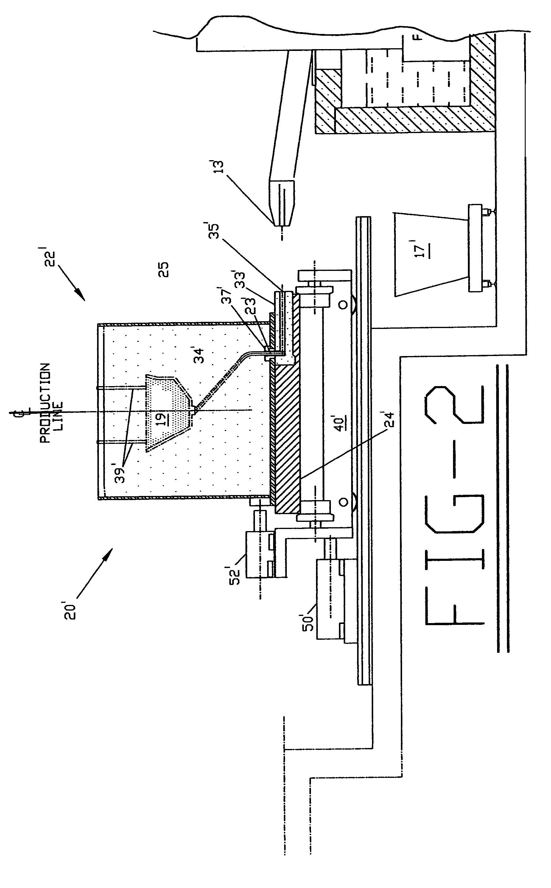
[0017]apparatus useful with the method of the present invention is shown in FIG. 3 generally at 20″. This third structural embodiment is similar to the second, also involving a lost foam casting technique. However, in this embodiment, the flow cutoff apparatus is different. The second hydraulic cylinder 52″ is mounted on the pumping station 10″. When the bottom filling of the mold assembly 22″ is completed, second hydraulic cylinder 22″ is actuated moving a knife-edge plunger 54″ to cutoff flow through runner 34″. As with the previous embodiments, when first hydraulic cylinder 50″ retracts shuttle car 40″, the molten metal remaining in the metal entrance 35″ below the cutoff point will drain into the catch ladle 17″.


PUM

PropertyMeasurementUnit
Flow rateaaaaaaaaaa

Abstract

An offset mold process deflects a mold assembly being conveyed along a first path laterally of that path into engagement with a nozzle using a shuttle car. Molten metal is pumped into the mold assembly, which is either a cope and drag mold or a lost foam mold, from below the molded part to eliminate eddy currents which can create incongruities in the molded part. One method of flow cutoff involves movement of a first mold component relative to the bottom board cuts off the flow of molten metal and locks the mold fill in the mold assembly. A second method of flow shutoff usable in the lost foam process involves the engagement of a flow cutoff plunger to cut the flow stream once filling the mold has been completed. In both the cope and drag and lost foam apparatuses, withdrawal of the shuttle car enables molten metal in the feed line to drain into a catch ladle obviating the need to burn embedded sand from the scrap prior to its recycling into the melt.

Description

BACKGROUND AND SUMMARY OF THE INVENTION[0001]The present invention is directed to the field of casting molten metal. More particularly, the present invention is directed to a process for bottom-filling a mold cavity and, then, offsetting the mold relative to the bottom board to cut off flow of the pumped metal and trap the mold fill.[0002]Conventional mold-filling methods involve filling a sand mold from the top through a sprue hole. Such a technique can result in creation of eddy currents which produce defects in the casting. If the defect goes beneath the surface, or if the article is a precision casting, such eddy currents can require scrapping of the entire casting.[0003]At least one attempt to combat these difficulties is taught in U.S. Pat. No. 5,230,379 to Voss. In the Voss patent, clamps and seals are provided to enable the molten metal to be drawn into the mold cavity from the bottom using a vacuum assist. Once the mold is completely filled, the mold can be displaced relati...

Claims


Application Information

Patent Timeline
IPC IPC(8): B22D18/06
CPCB22D18/04
Inventor EVANS, DWIGHTTACCONE, LEGAL REPRESENTATIVE, RUSSELLTACCONE, SR., DECEASED, RUSSELL
Owner EVANS DWIGHT
Why Eureka
Try Eureka