Heat exchanger exhaust gas recirculation cooler

a heat exchanger and exhaust gas technology, applied in indirect heat exchangers, machines/engines, light and heating apparatus, etc., can solve the problems of trapped vapor pockets, poor cooler thermal efficiency, and conventional heat exchangers, and achieve the effect of reducing or eliminating deficiencies of conventional approaches

Inactive Publication Date: 2007-05-08
DETROIT DIESEL CORP
View PDF20 Cites 28 Cited by
  • Summary
  • Abstract
  • Description
  • Claims
  • Application Information

AI Technical Summary

Benefits of technology

[0007]The present invention generally provides new, improved and innovative techniques for heat exchangers. The present invention generally provides a system and a method for heat exchangers that may reduce or eliminate deficiencies of conventional approaches such as thermal stress in critical areas at the inlet, local “hot spots” due to stagnant water flow areas by the hot passage, poorly shaped return tank and poor flow distribution, excessive gas pressure loss through the cooler, trapped vapor pockets (e.g., bubbles) and film boiling in liquid coolant, poor heat rejection, re-circulation on the inlet side of the header tank and non-uniform gas mass flux to the inlet tubes, re-circulation of coolant in the heat exchanger (in particular, re-circulation of coolant at the turnaround section), excessive coolant flow short circuit velocities, and reduced coolant flow across the gas tubes.

Problems solved by technology

However, conventional heat exchangers have a number of deficiencies.
The deficiencies of conventional heat exchangers include thermal stress in critical areas at the inlet which can cause fractures and failures of the heat exchanger, local “hot spots” due to stagnant water flow areas by the hot passage, poorly shaped return tank and poor flow distribution, excessive gas pressure loss through the cooler thereby causing poor cooler thermal efficiency, trapped vapor pockets (e.g., bubbles) and film boiling in liquid coolant, poor heat rejection, re-circulation on the inlet side of the header tank and non-uniform gas mass flux to the inlet tubes, re-circulation of coolant in the heat exchanger (in particular, re-circulation of coolant at the turnaround section), and excessive coolant flow short circuit (i.e., coolant that does not flow past the gas flow tubes) velocities (and reduced coolant flow across the gas tubes).

Method used


Image

  • Heat exchanger exhaust gas recirculation cooler
  • Heat exchanger exhaust gas recirculation cooler
  • Heat exchanger exhaust gas recirculation cooler

Examples


Embodiment Construction

)

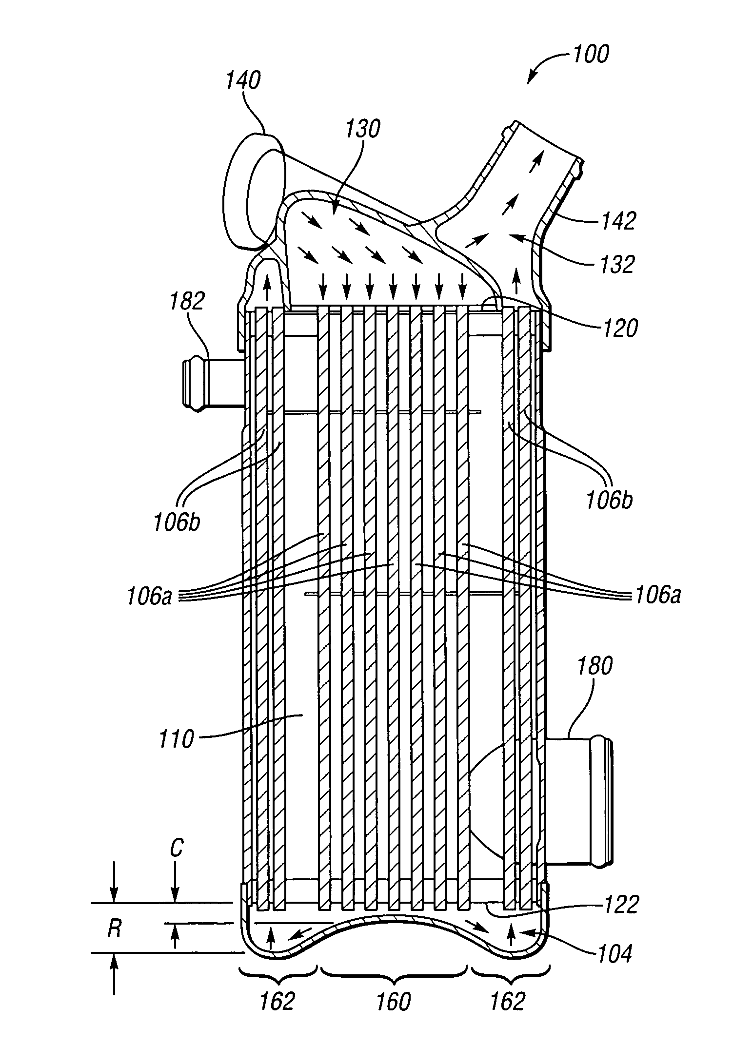
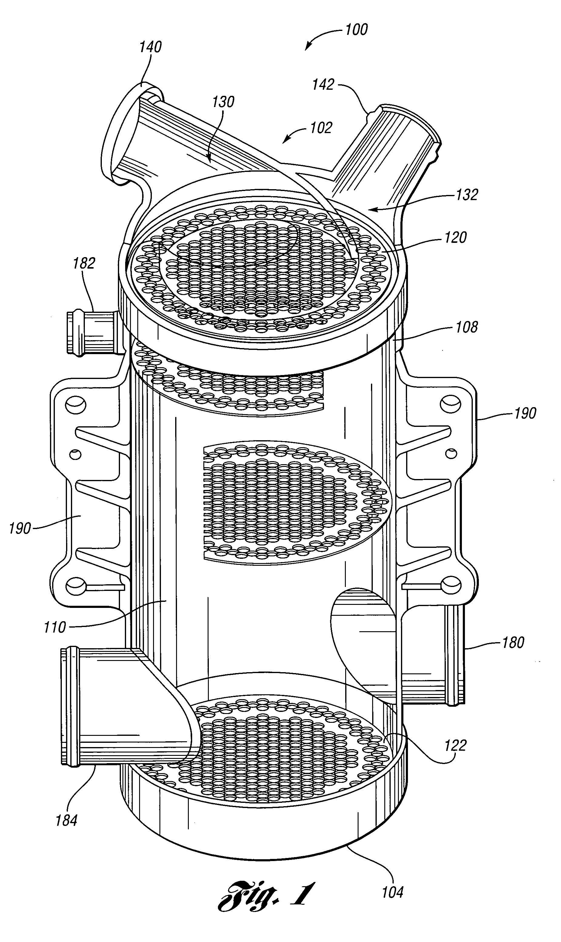
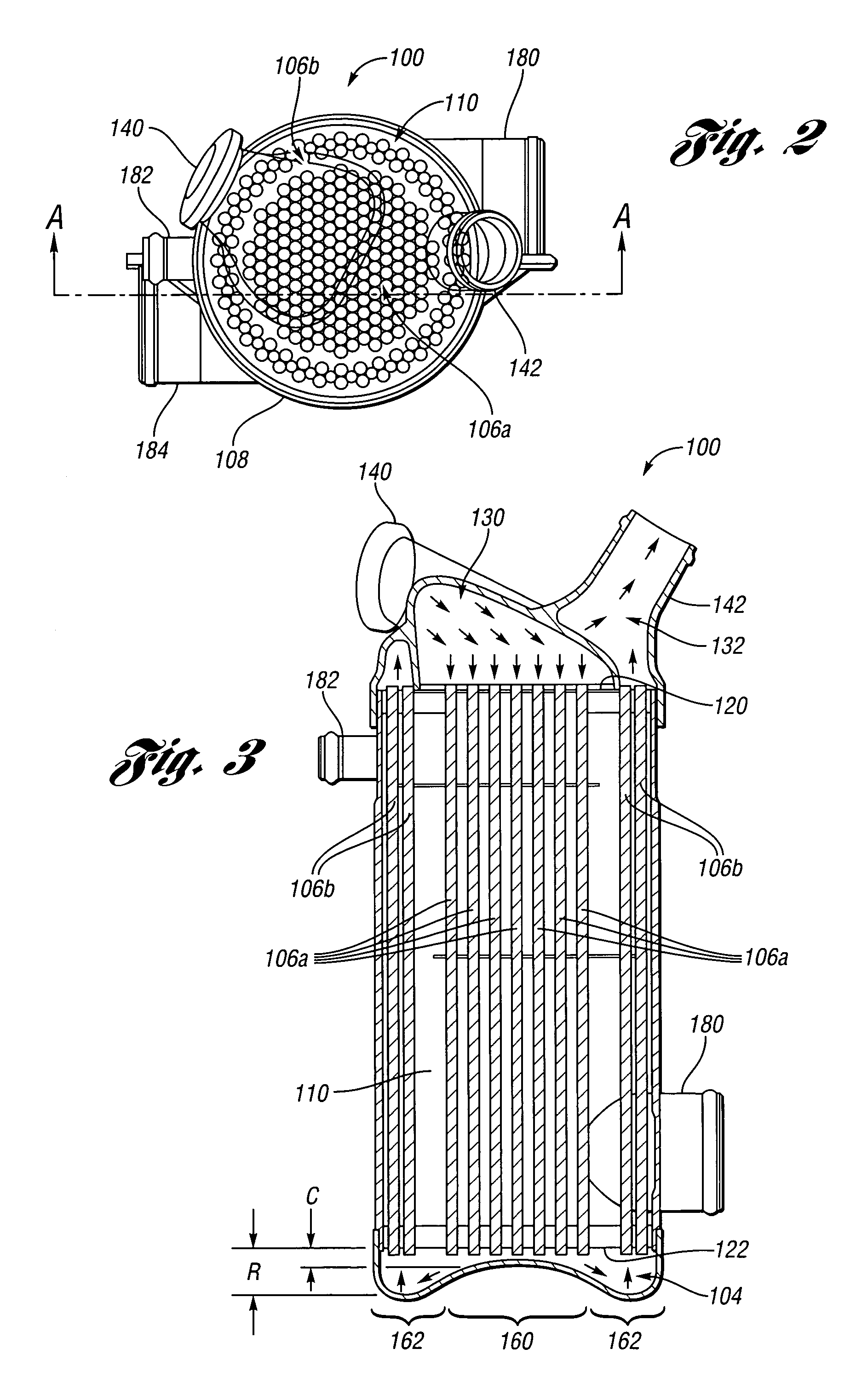
[0016]With reference to the Figures, the preferred embodiments of the present invention will now be described in detail. Generally, the present invention provides an improved system and an improved method for heat exchangers. In one example, the heat exchanger of the present invention may advantageously implemented as an exhaust gas recirculation (EGR) gas cooler. However, the heat exchanger of the present invention may used in connection with any appropriate application to transfer heat from a fluid on one side of a barrier to a fluid on the other side without bringing the fluids into direct contact. Heat exchangers implemented in accordance with the present invention may be used with several types of fluids, for example: air-to-air, air-to-water or water-to-water (or exhaust gas, coolant etc.), fluid to solid or semi-solid, etc. or combination thereof as appropriate to meet the design criteria of a particular application.

[0017]The present invention generally provides for having a...


PUM


Abstract

A two-pass, loop flow heat exchanger includes an inlet plenum that receives a fluid to be cooled, a housing, a plurality of inlet flow passages substantially centrally positioned within the housing and having a first end fluidly coupled to the inlet plenum to receive the fluid, a turnaround plenum fluidly coupled to a second end of the inlet flow passages for reversing the flow of the fluid, a plurality of outlet flow passages peripherally positioned within the housing and having a first end fluidly coupled to the turnaround plenum, and an outlet plenum fluidly coupled to a second end of the outlet flow passages to present the fluid.

Description

BACKGROUND OF THE INVENTION[0001]1. Field of the Invention[0002]The present invention relates to a system and a method for a heat exchanger.[0003]2. Background Art[0004]Heat exchanger assemblies, such as an automobile radiator, an exhaust gas recirculation (EGR) cooler, and the like are typically used to transfer heat from a fluid on one side of a barrier to a fluid on the other side without bringing the fluids into direct contact. Heat exchangers are used with several types of fluids, for example: air-to-air, air-to-water or water-to-water (or exhaust gas, coolant, etc.).[0005]However, conventional heat exchangers have a number of deficiencies. The deficiencies of conventional heat exchangers include thermal stress in critical areas at the inlet which can cause fractures and failures of the heat exchanger, local “hot spots” due to stagnant water flow areas by the hot passage, poorly shaped return tank and poor flow distribution, excessive gas pressure loss through the cooler thereb...

Claims


Application Information

Patent Timeline
Patent Type & Authority Patents(United States)
IPC IPC(8): F28D7/12
CPCF02M25/0734F02M25/0737F28D7/1638F28F1/426F28D21/0003Y02T10/121F28F2210/06F02M26/29F02M26/32F28D1/0408F28D1/05325F28D1/05341F28D1/05391F28D7/1607F28F1/022
Inventor DANIELSSON, DENNIE BENGT-AKEDICEA, MARK LOUIS
Owner DETROIT DIESEL CORP
Why Eureka
Try Eureka