Seal assembly

a sealing assembly and sealing technology, applied in the direction of fluid pressure sealing joints, engine seals, pipe joints, etc., can solve the problems of reducing the physical strength of the carrier, affecting the sealing characteristics of the seal, and affecting the sealing effect of the seal,

Inactive Publication Date: 2007-05-08
FEDERAL MOGUL WORLD WIDE LLC
View PDF27 Cites 33 Cited by
  • Summary
  • Abstract
  • Description
  • Claims
  • Application Information

AI Technical Summary

Benefits of technology

[0008]The subject invention provides a sealing assembly that overcomes or greatly minimizes the deficiencies of the known prior seal assemblies discussed above. A seal assembly constructed according to the present invention has greater longevity as a result of the limited compression of the sealing bead (i.e., at most 40%). By designing a seal that operates at 40% or less compression, the present invention overcomes the challenges of prior seals by avoiding cracking or rupturing and loss of elasticity at compressions exceeding 40%. The low compression seals of the present invention further enable those who service a vehicle or clamped components to reuse the seal since its integrity has not been compromised by prolonged over-compression as with the prior seals which must be routinely replaced at time of service.

Problems solved by technology

This is particularly problematic with gasket applications since it calls for a fairly thick carrier to accommodate the deep groove for the sealing beads.
Not all applications can accommodate such a thick carrier, particularly certain automotive applications where there is a constant trend toward making engines and related components more compact, allowing for less and less space between mating components to achieve a seal.
One additional draw back to the deep groove approach for protecting sealing beads on carriers against over-compression is that the deep groove in combination with a thinner carrier reduces the physical strength of the carrier and may impair the sealing characteristics of the seal.
One disadvantage to this approach is that the seal material is displaced in opposite directions, putting undue stress on the gasket material which could lead to undesirable fatigue or possibly rupture over time.

Method used


Image

  • Seal assembly
  • Seal assembly
  • Seal assembly

Examples


Embodiment Construction

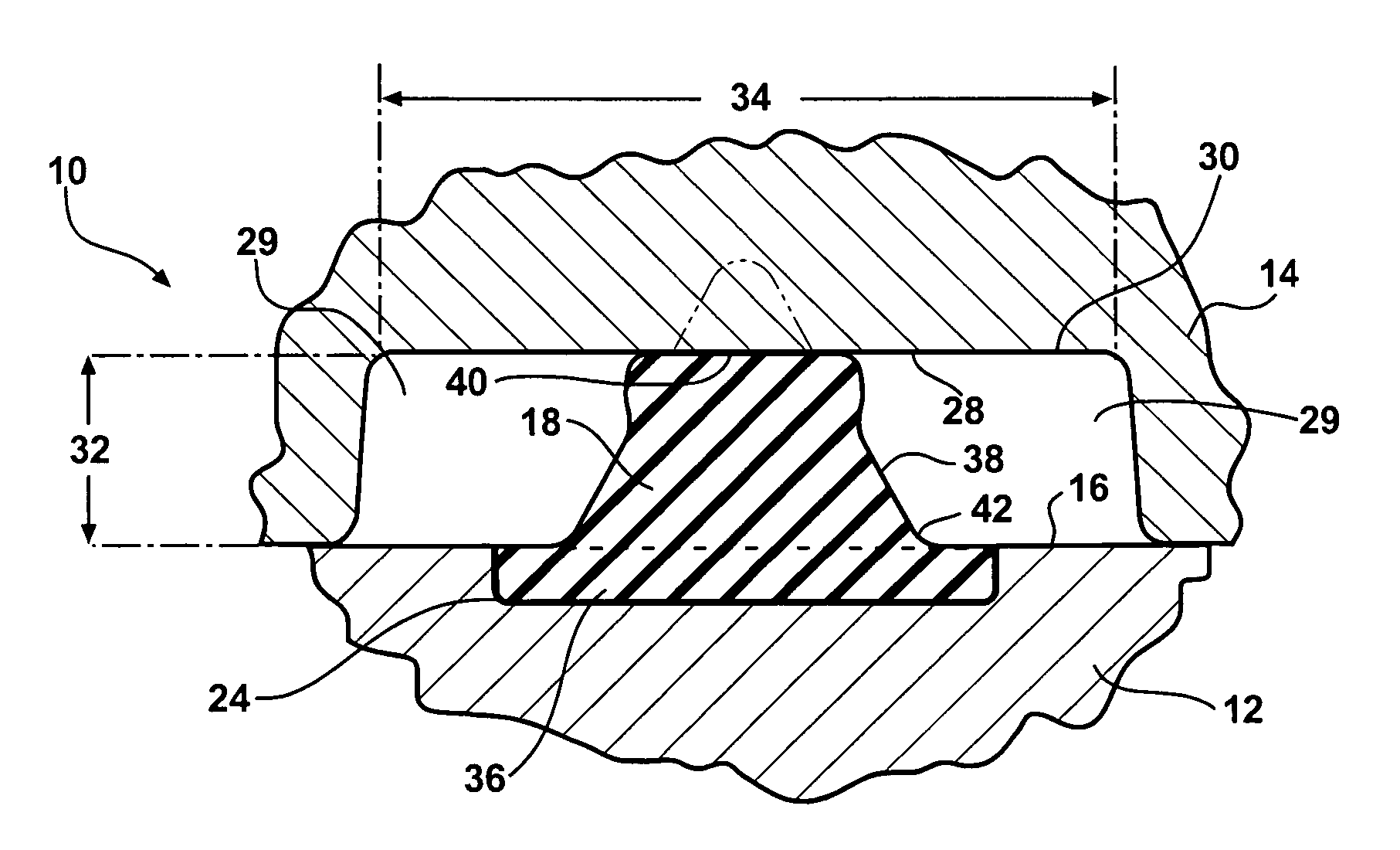
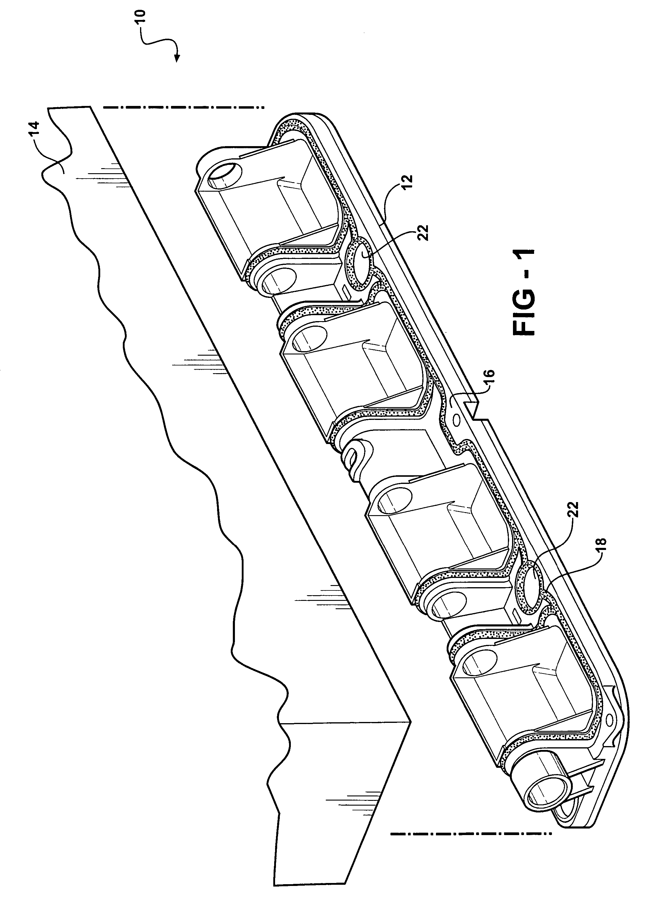
[0014]A sealing assembly constructed according to a first presently preferred embodiment of the invention is shown generally at 10 in FIG. 1. The sealing assembly 10 includes a first component 12 and a second component 14 moveable into and out of mating engagement with the first component 12 to form a seal therebetween. The invention contemplates within its scope that such a seal assembly 10 can be used with any of a number of components, but has particular application to providing a seal between automotive components, such as between a throttle body and a mating component, a water pump housing and a block, a valve cover and a head, an oil pan and the block and similar static sealing applications, and may have application in other sealing environments such as between a head and the block provided the chosen materials can sustain the operating environment.

[0015]FIG. 1 illustrates a throttle body (first component) 12 that is to be bolted in fluid-tight relationship with the accompanyi...


PUM


Abstract

The subject invention discloses a sealing assembly that includes a first component and a second component moveable into and out of mating engagement to form a seal therebetween. The first component has a first sealing surface defining a groove and a sealing bead extends upwardly a predetermined height therefrom. The sealing bead is molded within the groove. The second component has a second sealing surface defining a recess for contacting the sealing bead. When the first and the second components are brought into mating engagement, the sealing bead compresses at most 40% of the predetermined height when the second sealing surface contacts the sealing bead.

Description

BACKGROUND OF THE INVENTION[0001]1. Technical Field[0002]The subject invention relates generally to static sealing assemblies, and more particularly to those having an elastomeric sealing bead extending upwardly from a first component to create a seal with a second component.[0003]2. Related Art[0004]Various static sealing assemblies are known for creating a fluid-tight seal between mating components. One common type of static seal is a gasket which typically includes a carrier formed of a metal, such as steel, or plastics material on which elongated beads of elastomeric sealing material are adhered. The carrier provides the rigid framework or backbone for properly locating and supporting the sealing beads which, when the components are clamped together, are compressed under pressure to form the fluid-tight seal. Another type of static seal omits the carrier such that the sealing bead is applied directly to the sealing face of one of the two components, but otherwise operates in the...

Claims


Application Information

Patent Timeline
Patent Type & Authority Patents(United States)
IPC IPC(8): F16J15/02
CPCF16J15/025
Inventor HURLBERT, DAVID JNIU, HAO SHIRLEYGORDON, WILLIAM TWATERS, ROBERT M
Owner FEDERAL MOGUL WORLD WIDE LLC
Why Eureka
Try Eureka