Seal assembly

Inactive Publication Date: 2006-02-02
FEDERAL MOGUL WORLD WIDE LLC
View PDF27 Cites 3 Cited by
  • Summary
  • Abstract
  • Description
  • Claims
  • Application Information

AI Technical Summary

Problems solved by technology

This is particularly problematic with gasket applications since it calls for a fairly thick carrier to accommodate the deep groove for the sealing beads.
Not all applications can accommodate such a thick carrier, particularly certain automotive applications where there is a constant trend toward making engines and related components more compact, allowing for less and less space between mating components to achieve a seal.
One additional draw back to the d

Method used


Image

  • Seal assembly
  • Seal assembly
  • Seal assembly

Examples


Embodiment Construction

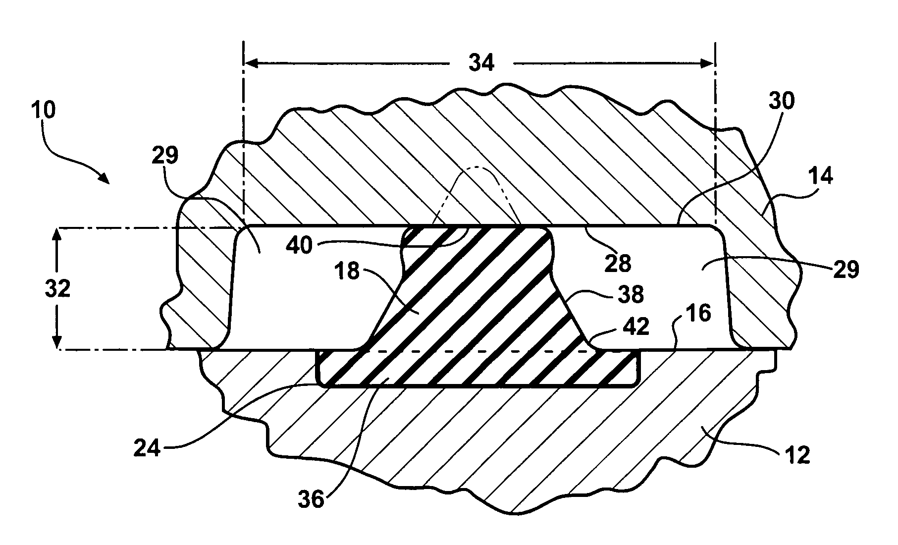
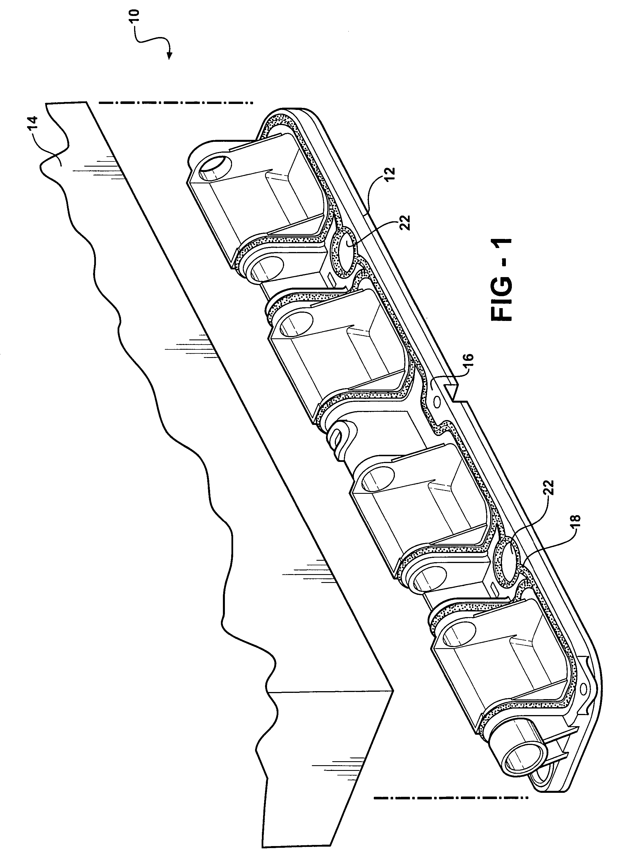
[0014] A sealing assembly constructed according to a first presently preferred embodiment of the invention is shown generally at 10 in FIG. 1. The sealing assembly 10 includes a first component 12 and a second component 14 moveable into and out of mating engagement with the first component 12 to form a seal therebetween. The invention contemplates within its scope that such a seal assembly 10 can be used with any of a number of components, but has particular application to providing a seal between automotive components, such as between a throttle body and a mating component, a water pump housing and a block, a valve cover and a head, an oil pan and the block and similar static sealing applications, and may have application in other sealing environments such as between a head and the block provided the chosen materials can sustain the operating environment..

[0015]FIG. 1 illustrates a throttle body (first component) 12 that is to be bolted in fluid-tight relationship with the accompa...


PUM


Abstract

The subject invention discloses a sealing assembly that includes a first component and a second component moveable into and out of mating engagement to form a seal therebetween. The first component has a first sealing surface defining a groove and a sealing bead extends upwardly a predetermined height therefrom. The sealing bead is molded within the groove. The second component has a second sealing surface defining a recess for contacting the sealing bead. When the first and the second components are brought into mating engagement, the sealing bead compresses at most 40% of the predetermined height when the second sealing surface contacts the sealing bead.

Description

BACKGROUND OF THE INVENTION [0001] 1. Technical Field [0002] The subject invention relates generally to static sealing assemblies, and more particularly to those having an elastomeric sealing bead extending upwardly from a first component to create a seal with a second component. [0003] 2. Related Art [0004] Various static sealing assemblies are known for creating a fluid-tight seal between mating components. One common type of static seal is a gasket which typically includes a carrier formed of a metal, such as steel, or plastics material on which elongated beads of elastomeric sealing material are adhered. The carrier provides the rigid framework or backbone for properly locating and supporting the sealing beads which, when the components are clamped together, are compressed under pressure to form the fluid-tight seal. Another type of static seal omits the carrier such that the sealing bead is applied directly to the sealing face of one of the two components, but otherwise operate...

Claims


Application Information

Patent Timeline
IPC IPC(8): F16L17/03
CPCF16J15/025
Inventor HURLBERT, DAVID J.NIU, HAO SHIRLEYGORDON, WILLIAM T.WATERS, ROBERT M.
Owner FEDERAL MOGUL WORLD WIDE LLC
Why Eureka
Try Eureka