Retractable seat device

a seat and seat technology, applied in the direction of movable seats, dismountable/non-movable seats, roofs, etc., can solve the problems of annoying users and generating abnormal noise, and achieve the effect of smooth engagemen

Active Publication Date: 2007-05-08
AISIN SEIKI KK
View PDF6 Cites 28 Cited by
  • Summary
  • Abstract
  • Description
  • Claims
  • Application Information

AI Technical Summary

Benefits of technology

[0008]An object of the present invention is to provide a retractable seat device which suppresses abnormal noise while a vehicle is in motion and thereby relieves annoyance of a user.
[0012]The second lock mechanism, which engages with the vehicle floor (second striker) next, engages with the second striker while the first end of the seat body is positioned relative to the vehicle floor by the first leg and the swinging movement of the second leg, which is unfolded by the link, is suppressed to as small an amount as possible. Accordingly, the second end of the seat body is positioned relative to the vehicle floor by the second leg. Since the swinging movement of the second leg is suppressed to as small an amount as possible, even though the second lock mechanism has the hook lock structure including the hook (that is, even though the second lock mechanism does not have an interlock structure), the reliability of the lock can be ensured. More specifically, a gap generated between the striker and the lock mechanism if the lock mechanism has an interlock structure can be eliminated. As a result, abnormal noise generated while the vehicle is in motion is reduced, and the user experiences less annoyance.
[0014]Accordingly, in the connection between the second leg and the second end of the link, the swinging movement of the second leg is allowed by the retaining pin and the long hole which receives the retaining pin. Therefore, when, for example, there are individual differences in the dimensions of the seat body and the arrangement of the second striker, the differences can be absorbed within the range of the swinging movement of the second leg. Thus, the second lock mechanism and the second striker can be smoothly engaged with each other.

Problems solved by technology

This gap C generates abnormal noise while the vehicle is in motion, which may annoy the user.

Method used


Image

  • Retractable seat device
  • Retractable seat device
  • Retractable seat device

Examples


Embodiment Construction

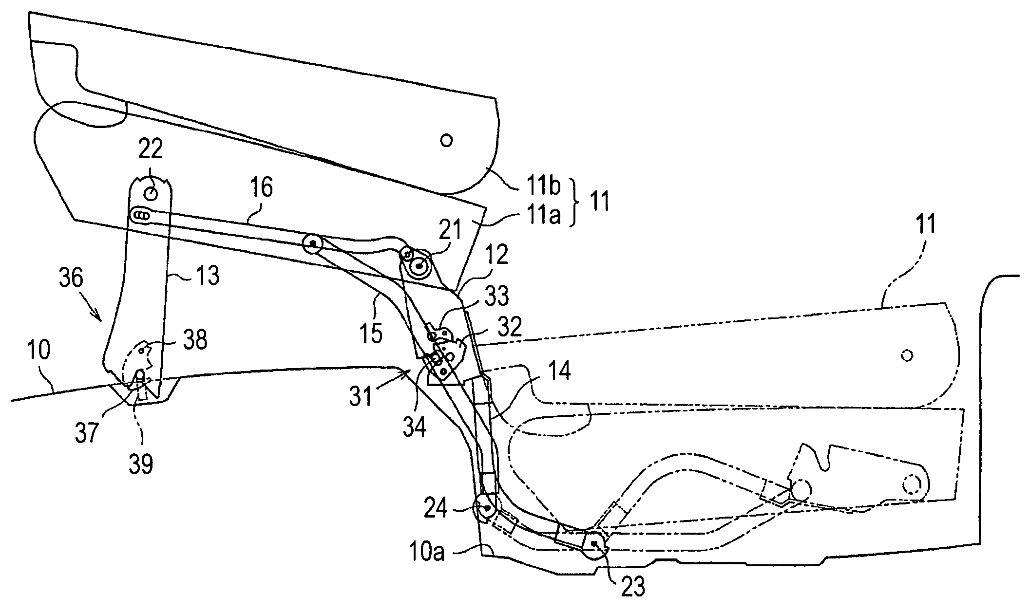
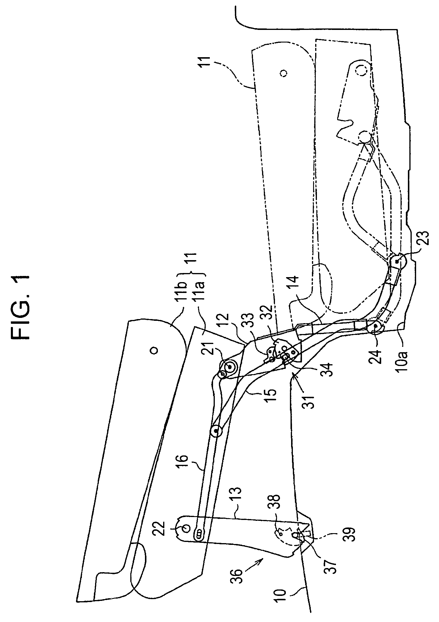
[0023]An embodiment of the present invention will be described below with reference to the drawings. FIG. 1 is a side view of a retractable seat device mounted on a vehicle, such as an automobile. The right side of FIG. 1 corresponds to the rear of the vehicle. As shown in FIG. 1, a storage recess 10a, which functions as a storage section, is formed in a rear region of a vehicle floor 10. A seat body 11, which functions as a seat, is either supported on the vehicle floor 10 in front of the storage recess 10a or stored in the storage recess 10a.

[0024]In detail, the retractable seat device includes the seat body 11, a rear leg 12 that functions as a first leg, a front leg 13 that functions as a second leg, a first arm 14, a second arm 15, and a link 16.

[0025]The seat body 11 includes a seat cushion 11a and a seat back 11b having an adjustable inclination angle with respect to the seat cushion 11a. The seat body 11 is stored in the storage recess 10a in such a manner that the seat bac...


PUM


Abstract

A retractable seat device includes a seat body having first and second ends rotatably connected to rear and front legs, respectively, first and second arms, and a link. When the first arm is rotated in a second direction, the rear leg and the front leg connected to the rear leg with the link are unfolded, a rear lock mechanism provided on the rear leg becomes engaged with a first striker provided on the vehicle floor, and then a front lock mechanism provided on the front leg becomes engaged with a second striker provided on the vehicle floor, so that the seat body is supported on the vehicle floor by the rear leg and the front leg. The rear lock mechanism has an interlock structure including a ratchet and a pawl, and the front lock mechanism has a hook lock structure including a hook.

Description

CROSS REFERENCE TO RELATED APPLICATIONS[0001]This application is based on and claims priority under 35 U.S.C. § 119 to Japanese Patent Application 2004-190071, filed on Jun. 28, 2004, the entire content of which is incorporated herein by reference.BACKGROUND OF THE INVENTION[0002]1. Field of the Invention[0003]The present invention relates to a retractable seat device.[0004]2. Description of the Related Art[0005]A retractable seat device disclosed in, for example, Japanese Unexamined Patent Application Publication No. 2001-347865 is known. This retractable seat device includes a seat body that can be stored in a storage recess provided in a vehicle floor when the seat body is not used. The state of the seat body is switched between the stored state and a usable state by moving the seat body around a rotation center provided on the vehicle floor. More specifically, legs (front and rear legs) for supporting the seat body in the usable state are arranged at the front and rear of the se...

Claims


Application Information

Patent Timeline
Patent Type & Authority Patents(United States)
IPC IPC(8): B60N2/02B60N2/015B60N2/30B60R5/04
CPCB60N2/01516B60N2/3011B60N2/3065B60N2/3079B60N2/309
Inventor YOKOYAMA, TAKASHIHOSHIHARA, NAOAKI
Owner AISIN SEIKI KK
Why Eureka
Try Eureka