Needle assembly with protective element

a technology of protective element and needle, which is applied in the direction of catheters, infusion needles, trocars, etc., can solve the problems of inability to rule out the risk of injury and difficulty in moving the needle by hand on the needle, and achieve the effect of facilitating hand actuation and preventing injury

Inactive Publication Date: 2007-05-08
B BRAUN MELSUNGEN AG
View PDF50 Cites 196 Cited by
  • Summary
  • Abstract
  • Description
  • Claims
  • Application Information

AI Technical Summary

Benefits of technology

[0004]The object of the invention is to design a protective device of the type mentioned at t...

Problems solved by technology

Because of the smallness of the protective element, it is difficult to move it by hand on the needle.
In addition...

Method used


Image

  • Needle assembly with protective element
  • Needle assembly with protective element
  • Needle assembly with protective element

Examples


Embodiment Construction

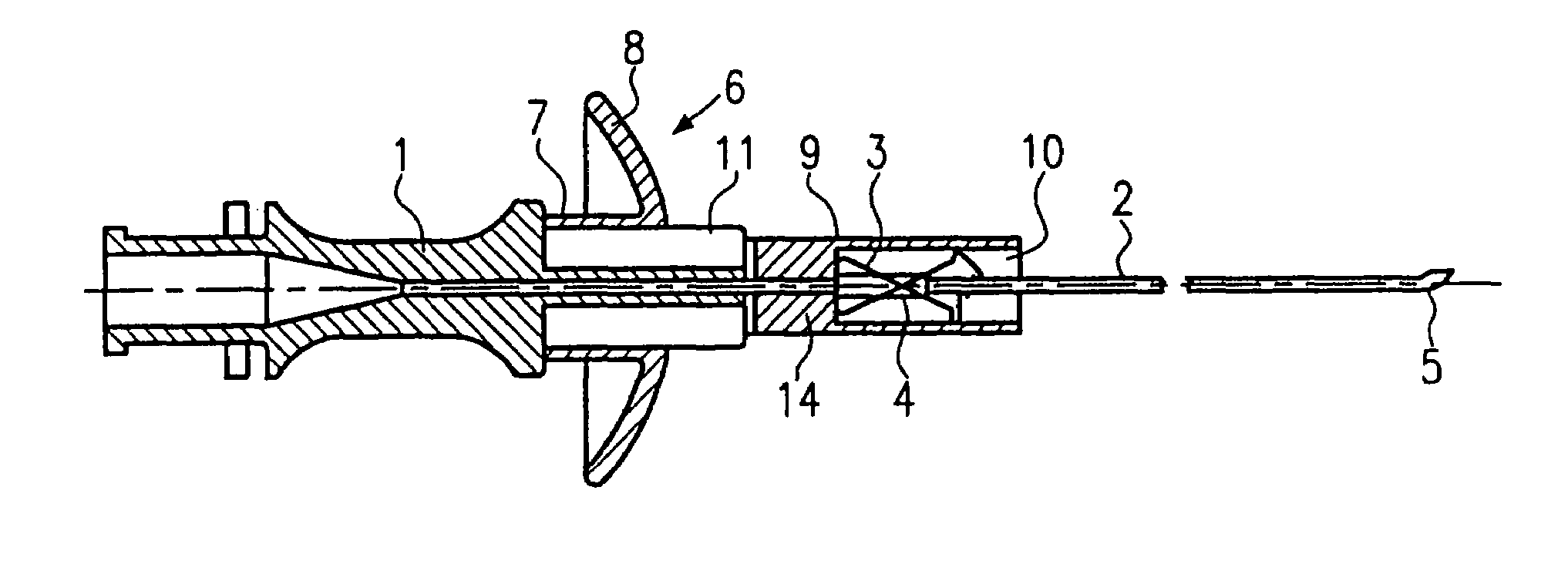
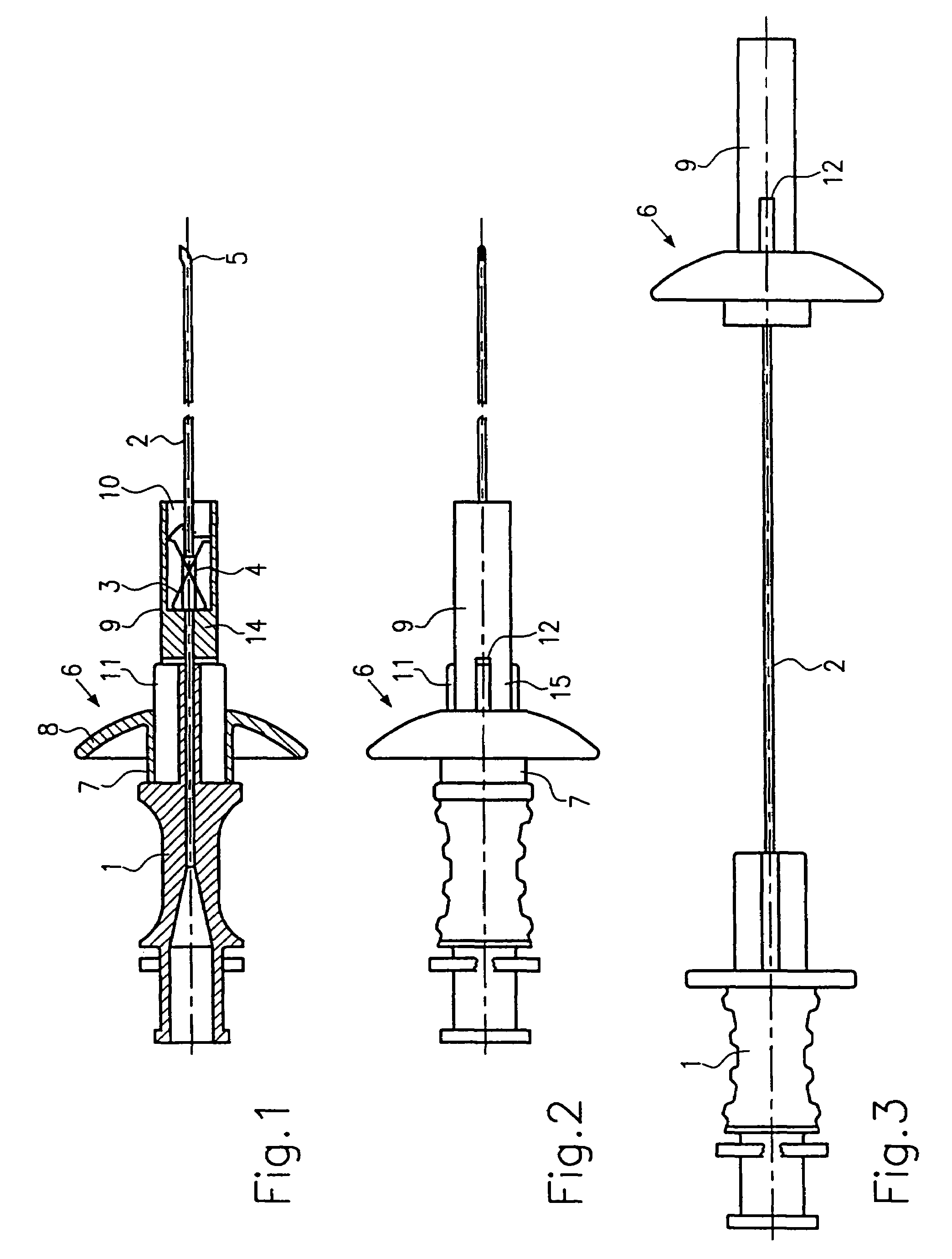
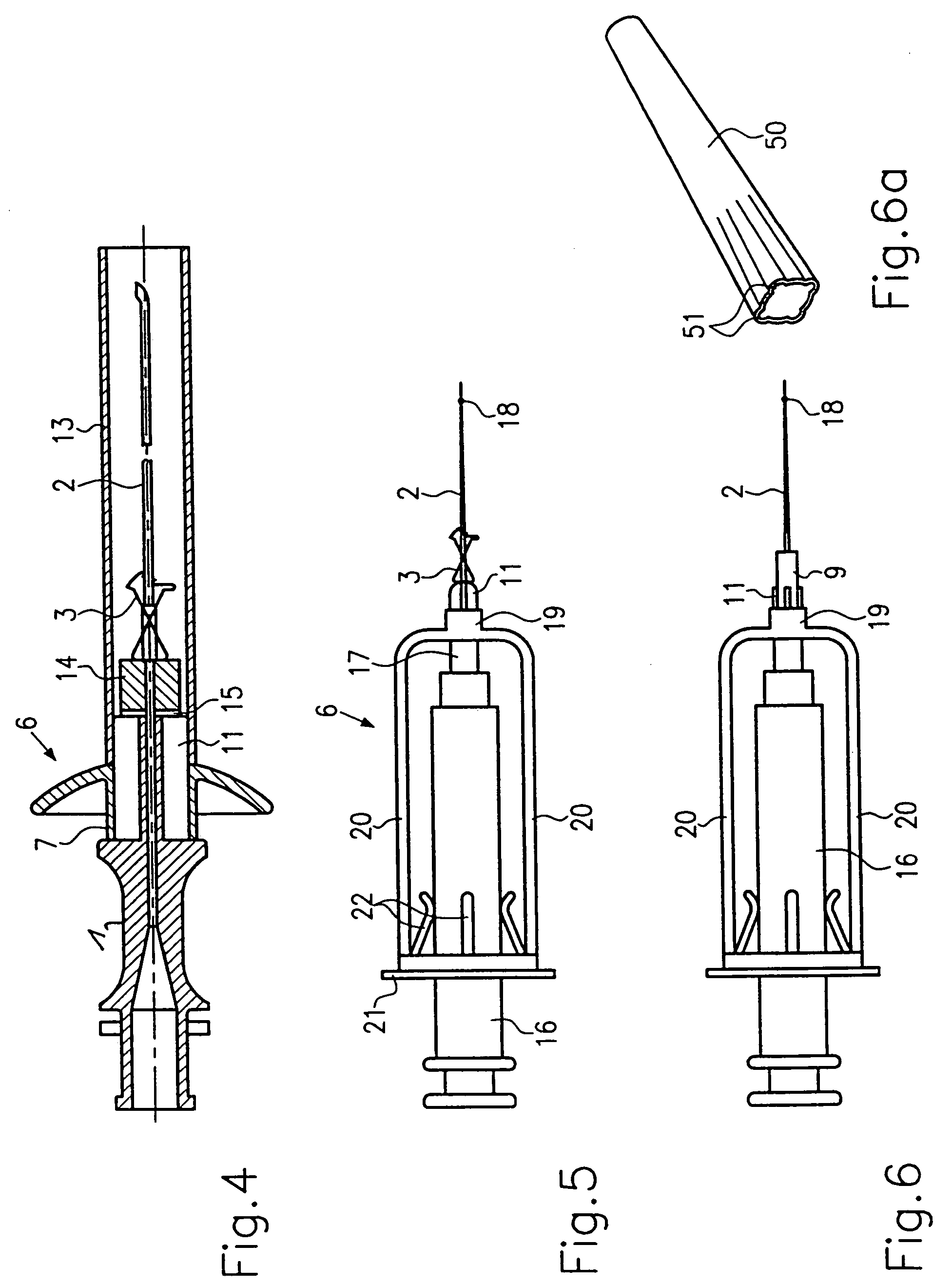
[0027]FIG. 1 shows a needle holder 1 in which a needle 2 is secured. Arranged on the shaft of the needle 2 there is a protective element 3 in the form of a spring clip with intersecting arms. Reference number 4 indicates a sleeve which can be moved with the protective element 3 along the needle shaft. In the illustrative embodiment shown, the tip 5 of the needle is designed with a curve in the manner of an epidural needle or a Huber needle, so that the sleeve 4, which has a smaller diameter than the curve on the needle tip, and, together with it, the protective element 3 and cannot be moved past the needle tip.

[0028]Arranged between needle holder 1 and protective element 3 there is a grip part 6 which, at the proximal end, has a hollow cylindrical portion 7 on which a radially protruding shield 8 is formed. On the front face of the shield 8 there is a cylindrical portion 9 whose distal end is hollow. In the standby position according to FIG. 1, the protective element 3 is arranged i...


PUM


Abstract

The invention relates to a protective device for an injection needle or infusion needle, comprising a needle holder at the proximal end of the needle, on whose shaft a protective element for the needle tip can be moved, said protective element being prevented, by an engagement device between the needle and the protective element, from being moved past the needle tip, and a grip part being provided between the protective element and the needle holder for the purpose of moving or securing the protective element.

Description

CROSS-REFERENCE TO RELATED APPLICATIONS[0001]This application claims priority of International Application No. PCT / EP02 / 02042, filed Feb. 26, 2002, entitled PROTECTIVE DEVICE FOR AN INJECTION NEEDLE, which claims the benefit of German Application No. 201 03 363.1, filed Feb. 26, 2001, the contents of which are expressly incorporated herein by reference.SUMMARY OF THE INVENTION[0002]The invention relates to a protective device for an injection needle or infusion needle according to the preamble of claim 1.[0003]A protective device of this kind is known for example from U.S. Pat. No. 4,929,241, in which a relatively small protective element is arranged on the needle and can be moved by a spring from the retracted position to the protection position on the needle tip, with elastic arms of the protective element engaging over the needle tip, while an engagement device on the protective element holds the latter on the needle shaft. Because of the smallness of the protective element, it i...

Claims


Application Information

Patent Timeline
IPC IPC(8): A61M5/178A61B17/34A61M5/158A61M5/32A61M25/06
CPCA61M5/3273A61M5/3275A61M25/0612A61M25/0637A61M5/3204A61M25/0625A61B17/3401A61M2025/0253A61M2005/1581A61M2005/3247
Inventor WOEHR, KEVINFUCHS, JURGEN
Owner B BRAUN MELSUNGEN AG
Why Eureka
Try Eureka