Threading/tapping control apparatus

a control apparatus and threading technology, applied in the direction of electric programme control, program control, instruments, etc., can solve the problems of large synchronization error, degraded threading precision, and synchronization error between workpiece and tool, so as to reduce synchronization error and reduce synchronization error

Active Publication Date: 2007-05-08
FANUC LTD
View PDF11 Cites 7 Cited by
  • Summary
  • Abstract
  • Description
  • Claims
  • Application Information

AI Technical Summary

Benefits of technology

[0009]An object of the present invention is to provide a threading / tapping control apparatus reducing synchronization error even if an operating speed changes due to a change of a command speed or an outside disturbance and reducing synchronization error in an acceleration / deceleration zone.

Problems solved by technology

If, however, in threading, the operating speed changes due to a change of the command or an outside disturbance, there is the problem that synchronization error occurs between the workpiece and the tool and the threading precision is degraded.
Further, in the case of tapping, if the delay of a servo system of an acceleration / deceleration zone becomes large, the synchronization error will become large and faster machining will become difficult.

Method used


Image

  • Threading/tapping control apparatus
  • Threading/tapping control apparatus
  • Threading/tapping control apparatus

Examples


first embodiment

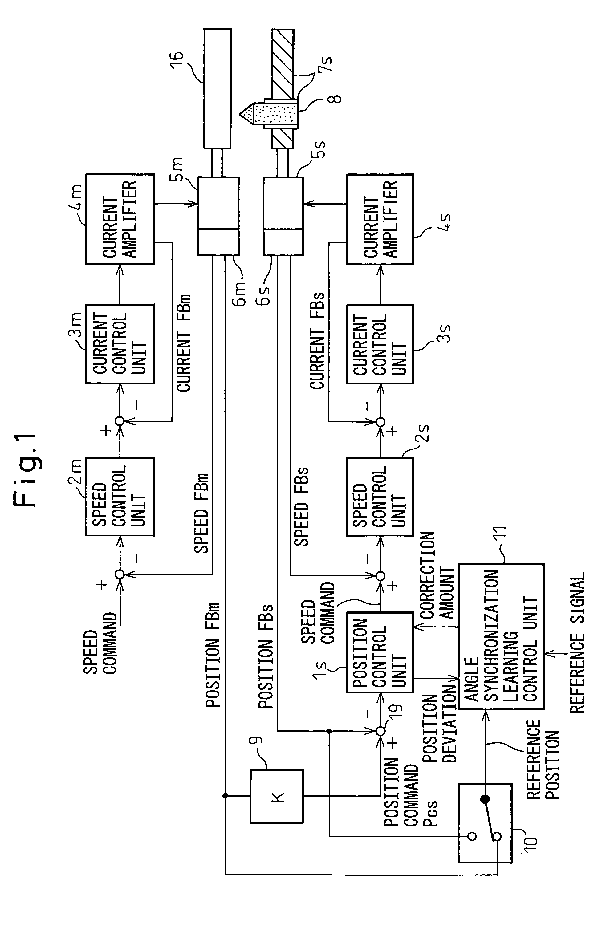
[0025]Below, an explanation will be given of embodiments of the present invention together with the drawings. FIG. 1 is a block diagram of the present invention. This embodiment is an example of threading a workpiece 16. In this example, a workpiece 16 is rotated by a master motor 5m, and a tool (cutting tool) 8 is moved in the axial direction of the center of rotation of the workpiece 16 by a ball screw / nut mechanism 7s driven by a slave motor 5s.

[0026]A speed command output from a host controller such as numerical control unit is subtracted by a speed feedback from a position and speed detector 6m for detecting the position and speed of the master motor 5m and attached to the master motor 5m to find the speed deviation. A speed control unit 2m performs proportional, integrated, or other speed loop control based on the speed deviation and finds a torque command (current command). This torque command (current command) is subtracted by a current feedback detected by a current detect...

second embodiment

[0055]The control system of the master motor 5m and the slave motor 5s basically resembles that of the second embodiment, but differs in the point that the position command Pcs to the slave motor 5s is found from the position command Pcm to the master motor 5m by a command processing means 14. Further, it is differs in the point that angle synchronization learning control units 13m′ and 13s′ provided in the master motor 5m and the slave motor 5s store the correction data at the time of the forward rotation (forward movement) and reverse rotation (backward movement) of the tapper 15, the correction data is selected according to the difference of the rotation direction, and the correction amount is found.

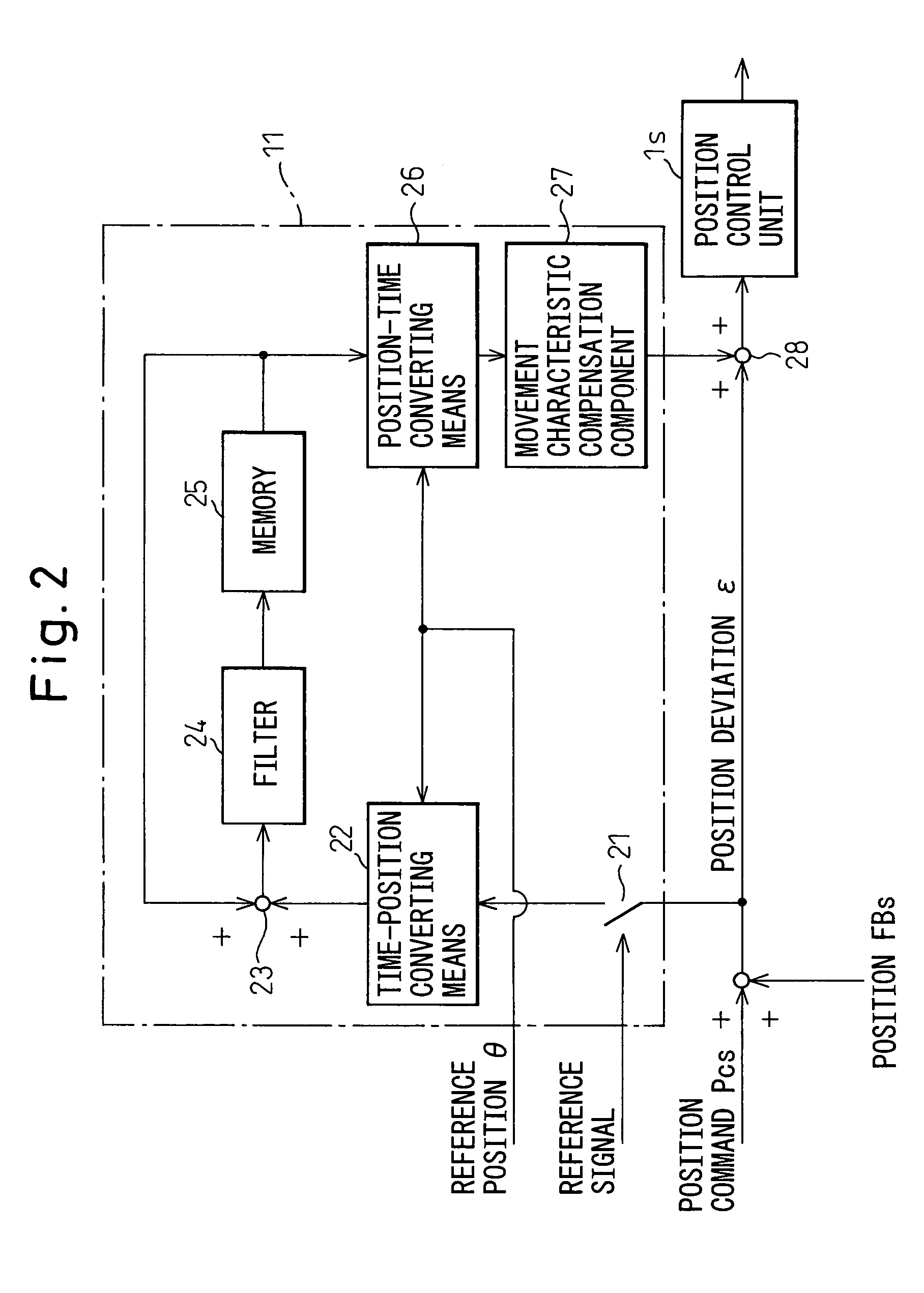
[0056]FIG. 8 is a detailed block diagram of the angle synchronization learning control units 13m′ and 13s′ in this third embodiment. The difference from the angle synchronization learning control units of the first and second embodiments of FIG. 2 resides in that the memory 25 is prov...

third embodiment

[0057]In this third embodiment, the tapper 15 is positioned at the position for tapping the workpiece 16, the position command Pcm to the master motor 5m is output to start the loop processing of the position, speed, and current including the learning control processing, and the master motor 5m and the slave motor 5s are synchronously driven. In this case, the processing with respect to the master motor 5m is the same as that of the flowchart of FIG. 5, the command position Pcm(n) to the master motor 5m is read at steps 100 and 101 and, at the same time, the position feedback of the master motor 5m is read and the position deviation ε is found at step 102. Further, the processing of step 103 and on is executed to control the master motor 5m.

[0058]Further, the processing with respect to the slave motor 5s reads the position feedback of the slave motor 5s at step 100 of FIG. 5. At step 101, the command position Pcm(n) to the master motor 5m is read. The command position Pcm(n) is mul...


PUM

PropertyMeasurementUnit
rotationaaaaaaaaaa
rotational speedaaaaaaaaaa
accelerationaaaaaaaaaa

Abstract

A workpiece is rotated by a master motor and a tool is linearly moved by a slave motor to cut a thread in the workpiece. Position feedback of the master motor is multiplied by a coefficient K and the result used as the position command of the slave motor. Provision is made of an angle synchronization learning control unit for storing one pattern cycle's worth of the correction data of the threading and adding the same to the position deviation. This control unit stores one pattern cycle's worth of the correction data corresponding to the position feedback of the master motor. The position is converted to the correction data corresponding to the time at that time based on the stored correction data to find the correction data and this is added to the position deviation.

Description

BACKGROUND OF THE INVENTION[0001]1. Field of the Invention[0002]The present invention relates to a threading / tapping control apparatus for synchronous control of a rotational shaft and a linear feed shaft when threading or tapping a workpiece.[0003]2. Description of the Related Art[0004]When threading a workpiece, the threading is carried out by rotating the workpiece while using a cutting tool to give a predetermined cut to the workpiece and making the cutting tool move relatively in the workpiece axial direction. In this case, the cutting tool must be made to move relatively with respect to the workpiece in the axial direction in synchronization with the rotation of the workpiece. Further, when tapping a workpiece by a tapper, the rotation of the tapper and the feed in the axial direction must be synchronized.[0005]In this threading, to synchronize the rotational shaft and the linear feed shaft, the method of detecting the rotational speed of the rotational shaft (spindle) rotatin...

Claims


Application Information

Patent Timeline
Patent Type & Authority Patents(United States)
IPC IPC(8): H02P5/46B23Q15/00B23G1/16G05B19/18G05B19/19
CPCG05B19/186G05B19/19G05B2219/41177G05B2219/41207G05B2219/42129G05B2219/45214G05B2219/45216
Inventor TOYOZAWA, YUKIOSONODA, NAOTO
Owner FANUC LTD
Why Eureka
Try Eureka