Shock absorber mounting assembly for a bicycle

a technology for mounting assemblies and shock absorbers, which is applied in the direction of folding cycles, bicycle equipment, cycles, etc., can solve the problems of uneven mounting and the axes of the mounting apertures of the main frame and the subframe often will not be perfectly aligned with one, so as to reduce the side load

Inactive Publication Date: 2007-05-15
SPECIALIZED BICYCLE COMPONENTS INC
View PDF20 Cites 3 Cited by
  • Summary
  • Abstract
  • Description
  • Claims
  • Application Information

AI Technical Summary

Benefits of technology

[0010]A preferred embodiment is a method for reducing side loads on a shock absorber mounted between movable portions of a bicycle frame. The method includes securing a first end of a shock absorber to a first portion of the bicycle frame and passing a support shaft, defining a shaft axis, through a mounting aperture in a second portion of the bicycle frame. The support shaft is also passed through a mounting eyelet on a second end of the shock absorber. The support shaft is supported relative to the second portion of the bicycle frame. A first portion of a spacer is located relative to the shock absorber. A second portion of the spacer is located relative to the support shaft such that the first and second portions contact one another along respective curved contact surfaces. The first and second portions of the spacer are secured in a position relative to one another to accommodate misalignment of the shaft axis and the shock axis.

Problems solved by technology

Due to variations and imperfections inherent in many manufacturing processes, the axes of the mounting apertures of the main frame and the sub-frame often will not be perfectly aligned with one another.
That is, the mounting apertures of the main frame and sub-frame are often not perfectly parallel to one another.
When the shock absorber is mounted to a bicycle frame having such misaligned mounting apertures, the moveable portions of the shock absorber tend to align with their respective support shaft, or bolt, and thus are misaligned with one another.
As a result, the forces applied to the shock absorber by the sub-frame and main frame may not be perfectly aligned with the longitudinal axis of the shock absorber and, therefore, a force component is applied to the shock absorber in a direction perpendicular to its longitudinal axis.
Side loading of the shock absorber causes wear and often premature failure of certain components of the shock absorber, such as various seal members, for example.

Method used


Image

  • Shock absorber mounting assembly for a bicycle
  • Shock absorber mounting assembly for a bicycle
  • Shock absorber mounting assembly for a bicycle

Examples


Embodiment Construction

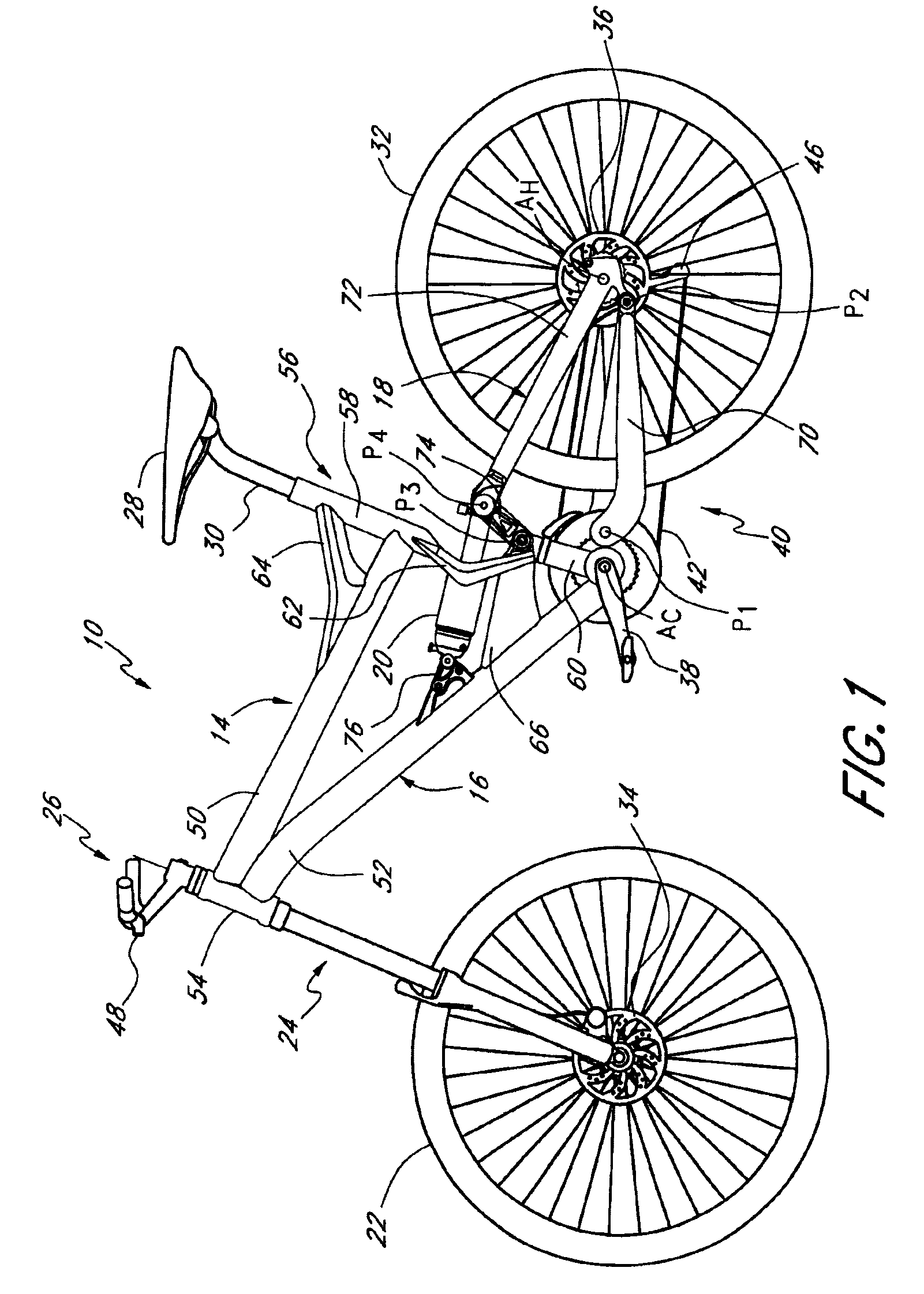
[0015]FIG. 1 illustrates a bicycle 10 including a shock absorber mounting assembly having certain features, aspects and advantages of preferred embodiments of the present invention. The overall bicycle 10 is described in general detail to assist in the understanding of certain beneficial features and advantages of the illustrated embodiment of the shock absorber mounting assembly 12. Details of the bicycle 10 that are not described herein may be assumed to be of a conventional construction or a suitable alternative construction, as will be appreciated by one of skill in the art. Although the present shock absorber mounting assembly is described herein with respect to a bicycle application, it is contemplated that the mounting assembly may be adapted for use with other vehicles incorporating shock absorbers, such as motorcycles or automobiles, for example.

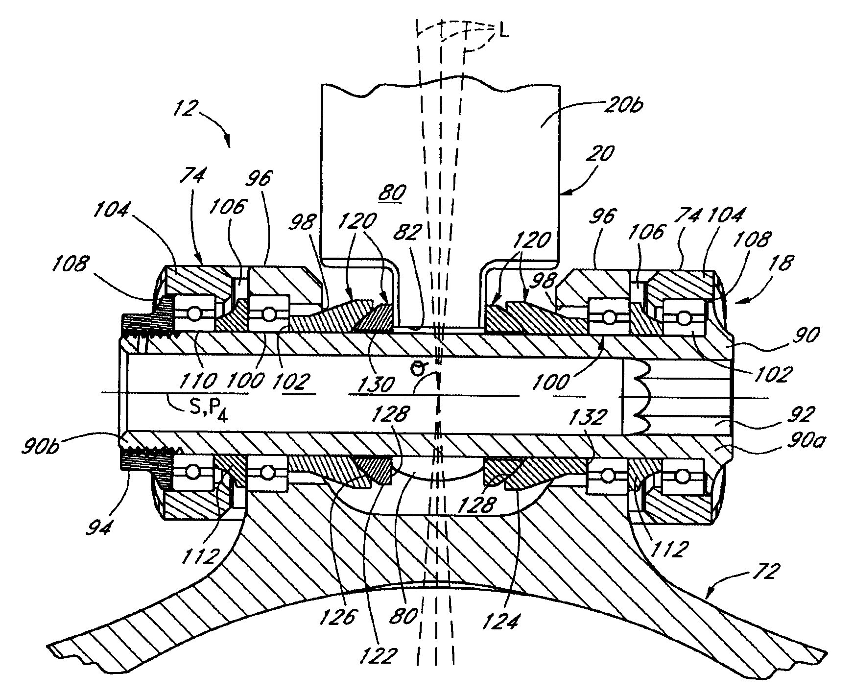
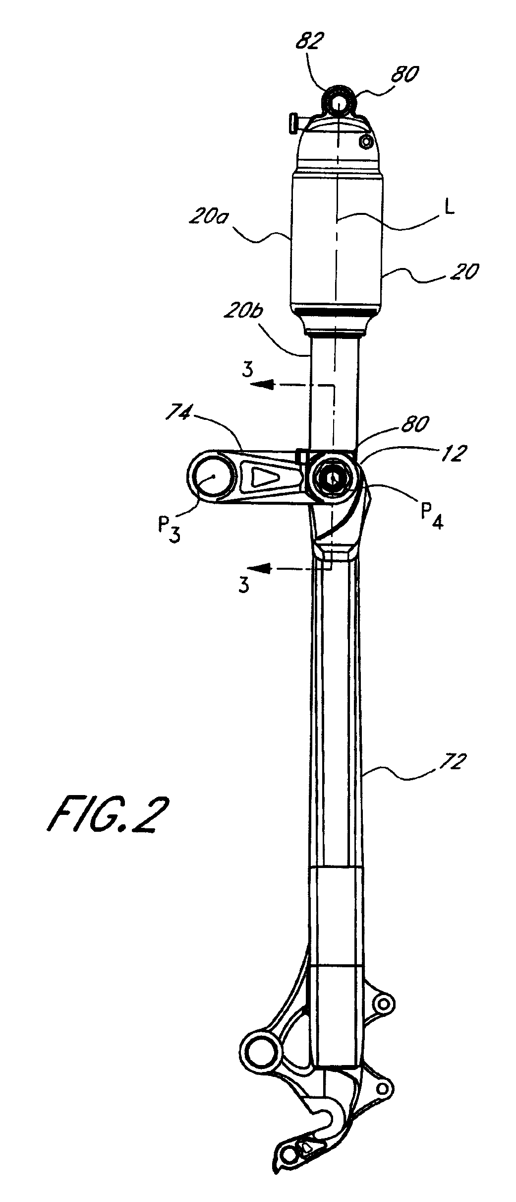
[0016]The bicycle 10 includes a frame assembly 14 which, preferably, includes a main frame portion 16 and a sub-frame portion 18. ...


PUM


Abstract

A system and method for mounting a shock absorber to a bicycle frame. The system preferably includes at least one spacer having a first spacer member and a second spacer member. Each of the first and second spacer members include a curved contact surface configured to contact the respective surface of the other spacer member. A first one of the spacer members is located relative to the bicycle frame and the second one of the space members is located relative to the shock absorber. The shock absorber and the second one of the spacer members may be rotated relative to the first spacer member and the bicycle frame to achieve a desired alignment between the shock absorber and the bicycle frame to compensate for misalignment between the mounting structures on the bicycle frame for a respective first and second ends of the shock absorber.

Description

BACKGROUND OF THE INVENTION[0001]1. Field of the Invention[0002]The present invention is related to shock absorber mounting assemblies in general and, more specifically, to a shock absorber mounting assembly well-suited for use in securing at least one end of a shock absorber to a bicycle.[0003]2. Description of the Related Art[0004]Many bicycles, especially those intended for off-road use, incorporate a suspension assembly associated with one or both of the front and rear wheels. In one common arrangement of a bicycle incorporating a rear wheel suspension assembly, the bicycle frame includes a main frame portion and a sub-frame portion, which is moveable relative to a main frame. The rear wheel is carried by the sub-frame and a rear shock absorber is connected at a first end to the main frame and at a second end to the sub-frame. The shock absorber is configured to provide a force tending to attenuate force inputs applied to the rear wheel of the bicycle and passed on to the main f...

Claims


Application Information

Patent Timeline
Patent Type & Authority Patents(United States)
IPC IPC(8): B62K25/20
CPCB62K25/286
Inventor CHAMBERLAIN, JASON L.
Owner SPECIALIZED BICYCLE COMPONENTS INC
Why Eureka
Try Eureka