Fall Protection Apparatus with a Mast and a Boom

Active Publication Date: 2016-12-29
TUFFBUILT PRODS
View PDF0 Cites 4 Cited by
  • Summary
  • Abstract
  • Description
  • Claims
  • Application Information

AI Technical Summary

Benefits of technology

[0060]It is of course necessary that the elongate member in the form of the strap remains connected to the mast at the inner end and to the coupling at the outer end to maintain continuity when the tube fractures. Thus preferably the tube is fastened to the support member by a pin passing through transverse holes in the tube and wherein the elongate member includes a hole therethrough by which the elongate member is connected to the pin. In order to ma

Problems solved by technology

However these are typically metal in construction with various arms a

Method used


Image

  • Fall Protection Apparatus with a Mast and a Boom
  • Fall Protection Apparatus with a Mast and a Boom
  • Fall Protection Apparatus with a Mast and a Boom

Examples


Embodiment Construction

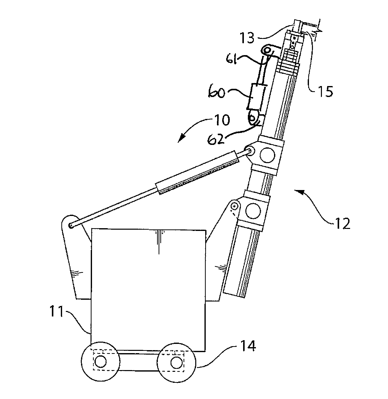
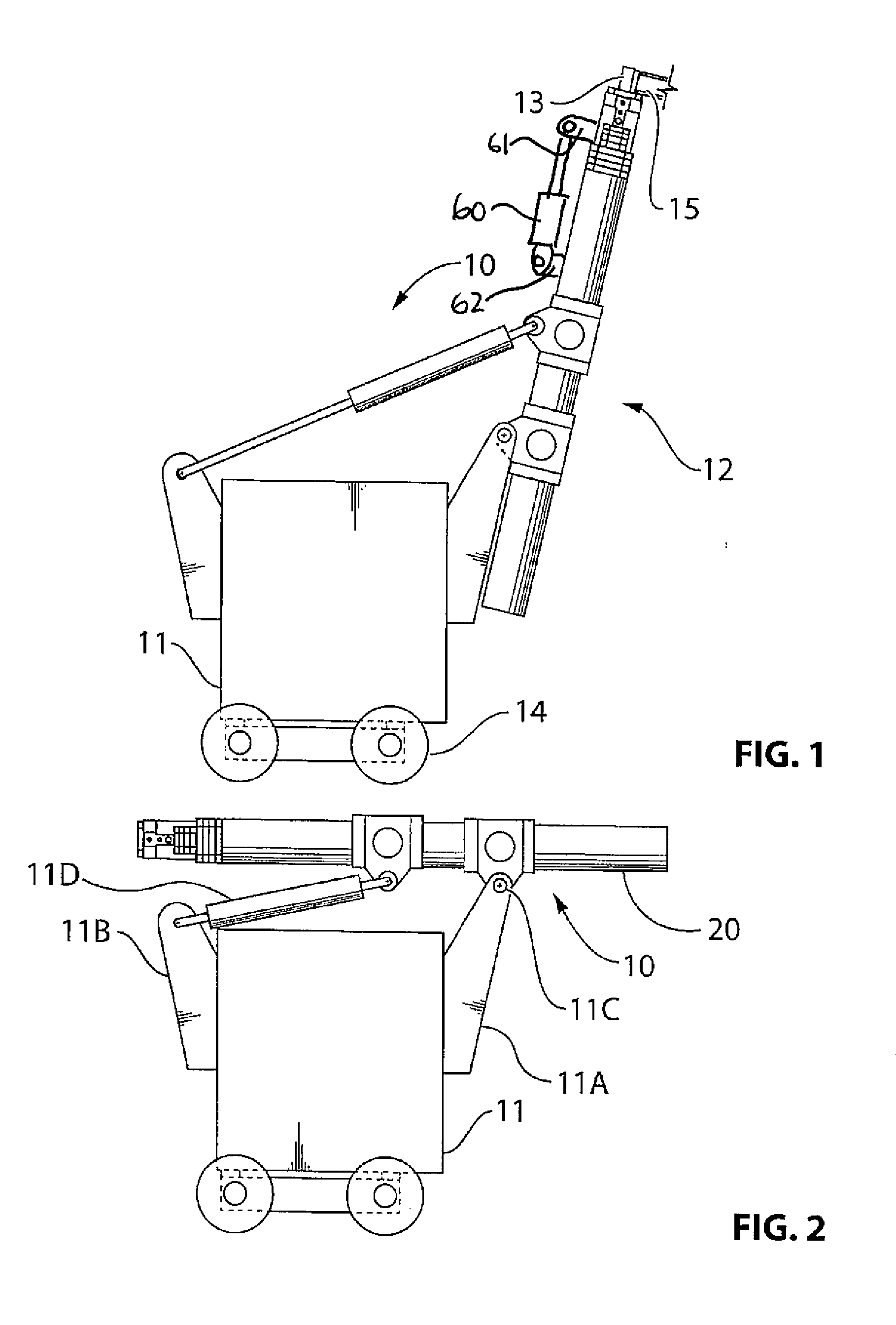
[0084]A fall restraint apparatus 10 comprises a support base 11, a mast 12, and a top support member 13 mounted on a top of the mast. The support base is preferably of the construction shown in U.S. Pat. No. 8,931,749 issued Jan. 13, 2015 of the present Applicant, the disclosure of which is incorporated herein by reference. In this case the base 11 may be mounted on a wheeled support or vehicle for movement to a required location, the wheeled support 14 being shown only schematically.

[0085]The support member 13 includes at least one and more typically two or four booms 15 attached to the support member 13 and extending outwardly to one side of the mast;

[0086]As shown in FIG. 10 or 11, each boom 15 includes a coupling member 16 in the form of a loop 16A attached to the boom at the outer end of the boom for receiving a fall restraint harness 16C of a worker attached by a cable 16B to the loop 16A.

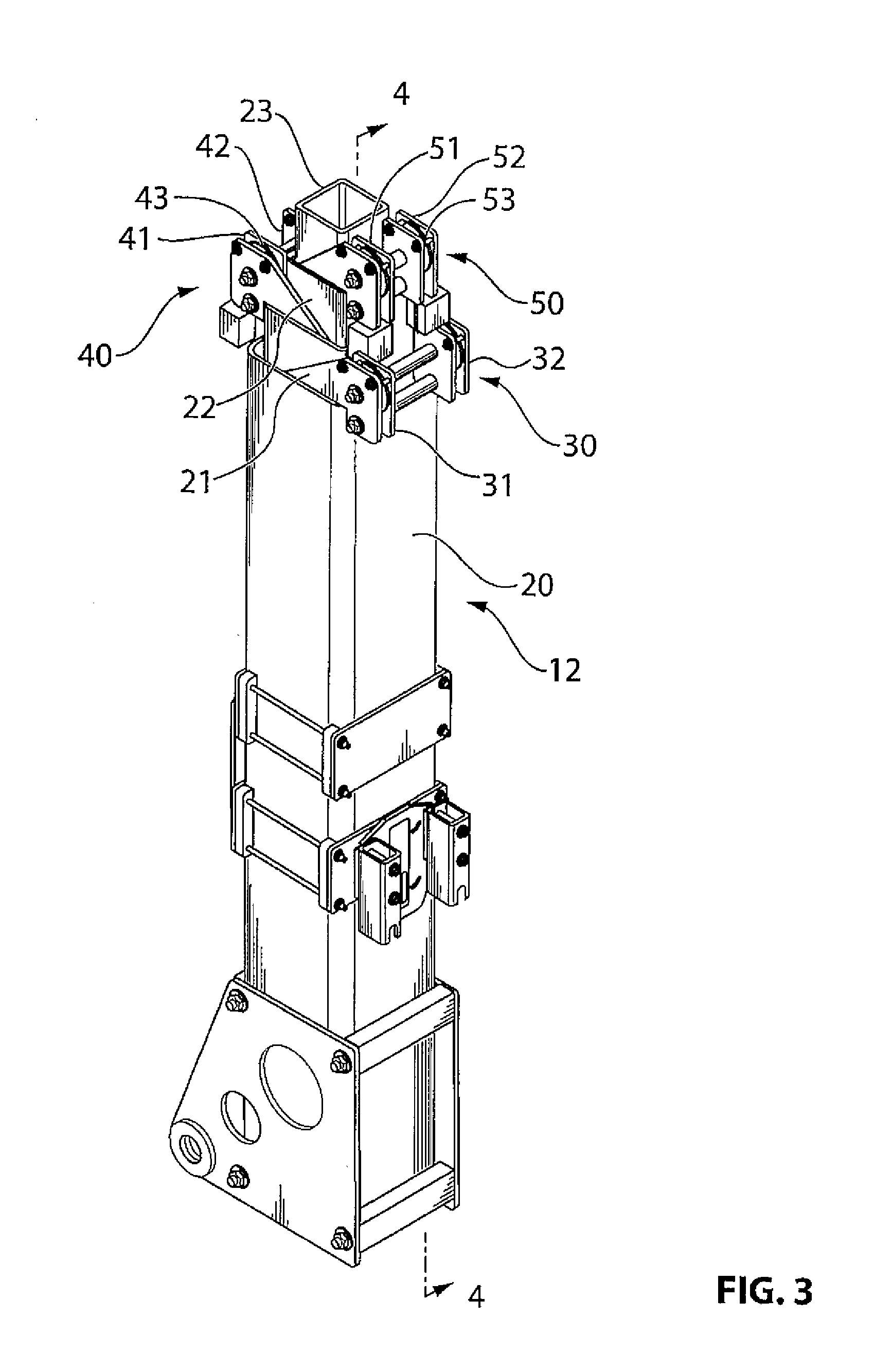
[0087]The mast 12 is telescopic so as to extend from the collapsed position shown in FIG....


PUM


Abstract

A fall protection apparatus includes a heavy support base with a pivotal mast having a top member for rotation around the axis of the mast carrying a series of booms pivotal about respective vertical axes, each having an end coupling member for receiving a fall restraint harness. Each boom is formed by a tube which fractures on a fall and an elongate stainless steel strap inside the tube which bends without fracturing. The mast includes a series of telescopic rectangular mast sections with a winch driven cable and pulley arrangement for extending the first section which acts to pull the second inner section to the extended position as the first inner section moves out of the outer section. Each section includes first and second pulleys mounted at the same face of the section with the cable located between the face of the section and the face of the next section.

Description

[0001]This application is a continuation in part of application Ser. No. 14 / 847,435 filed Sep. 8, 2015 and claims priority under 35 USC 119 (e) from Provisional application 62 / 183,964 filed Jun. 24, 2015.[0002]This invention relates to a fall protection apparatus with a telescopic mast where the mast is mounted on a support base and carries a boom at the upper end onto which a fall restraint harness can be mounted.BACKGROUND OF THE INVENTION[0003]Upstanding or vertical masts are commonly used to provide an upper end of the mast supported from the ground to which items may be attached which apply a horizontal load to the mast tending to topple the mast to one side.[0004]Where a permanent mounting is required, the mast can be inserted into a sleeve which can be connected to the structure of a building or the like by braces or by burying the sleeve in a concrete floor or other structural component.[0005]Portable bases can also be provided which allow the base and the mast carried there...

Claims


Application Information

Patent Timeline
IPC IPC(8): A62B35/00
CPCA62B35/0068A62B35/04E04G21/3204E04G21/329A62B35/0006E04H12/182F16M11/42
Inventor VETESNIK, JAN
Owner TUFFBUILT PRODS
Why Eureka
Try Eureka