Engine apparatus and method for reducing a side load on a flying object

a technology for flying objects and engine components, applied in the direction of marine propulsion, vessel construction, turbine/propulsion engine ignition, etc., can solve the problem of high side load and distribution, and achieve the effect of reducing side load

Inactive Publication Date: 2015-01-27
DEUTSCHES ZENTRUM FUER LUFT & RAUMFAHRT EV
View PDF12 Cites 4 Cited by
  • Summary
  • Abstract
  • Description
  • Claims
  • Application Information

AI Technical Summary

Benefits of technology

[0011]In accordance with an embodiment of the invention, there is provided an engine apparatus in which side loads are reduced.
[0037]By use of the skirt, the intake cross-section is increased so that a larger volume of air can be taken in. Furthermore, said volume of air has a higher velocity. It is thereby possible to damp or reduce asymmetric fluctuations both in a separation zone and in a separated region, and the side load is reduced.

Problems solved by technology

The asymmetric distribution leads to high side loads.

Method used


Image

  • Engine apparatus and method for reducing a side load on a flying object
  • Engine apparatus and method for reducing a side load on a flying object
  • Engine apparatus and method for reducing a side load on a flying object

Examples


Embodiment Construction

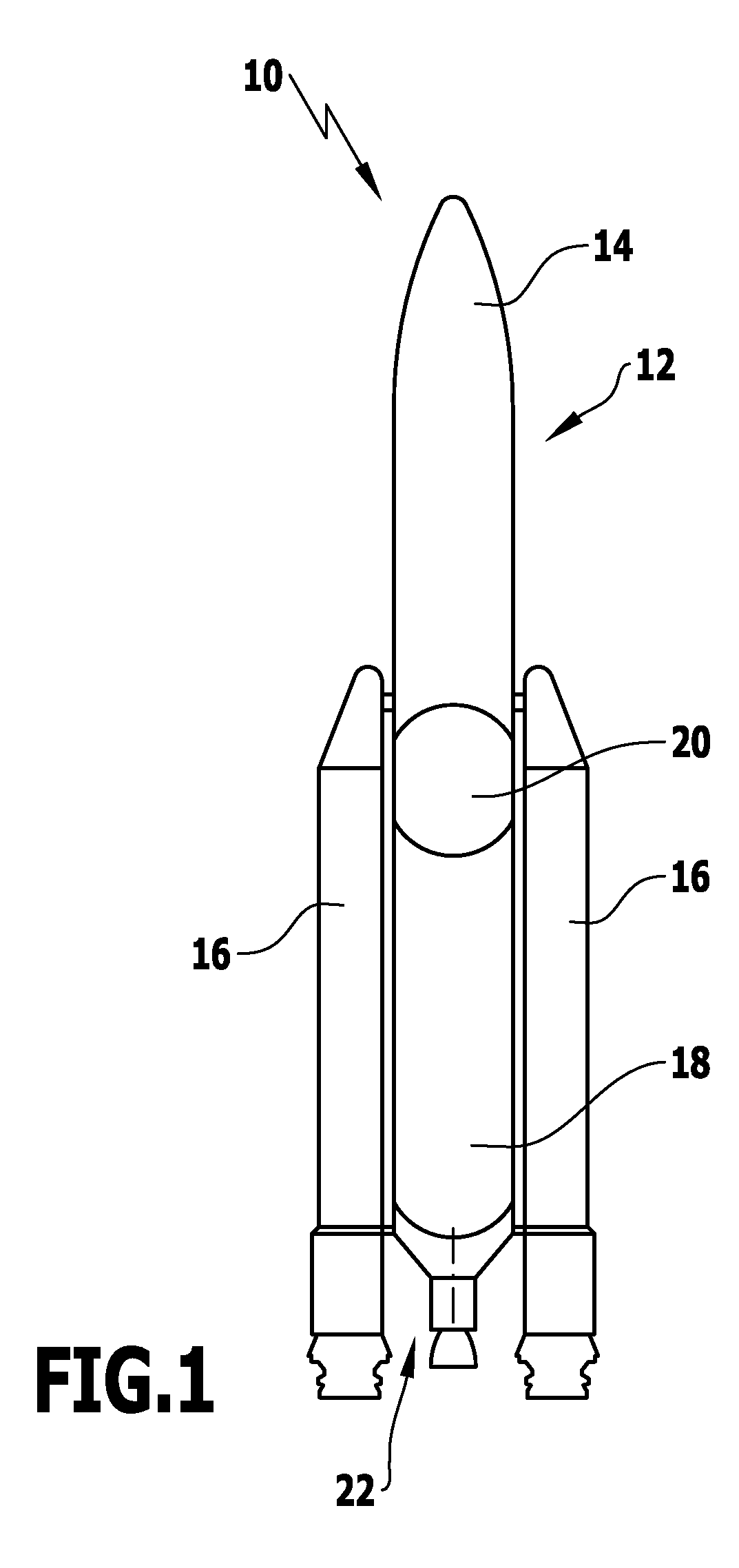
[0046]An exemplary embodiment of a flying object 10, shown schematically in FIG. 1, is a rocket. Said rocket comprises a main body 12 by which a payload unit 14 can be transported. The rocket has two solid boosters 16 for example.

[0047]The main body 12 comprises a first tank 18 and a second tank 20. The first tank 18 contains a fuel, such as liquid hydrogen. The second tank 20 holds an oxidizer.

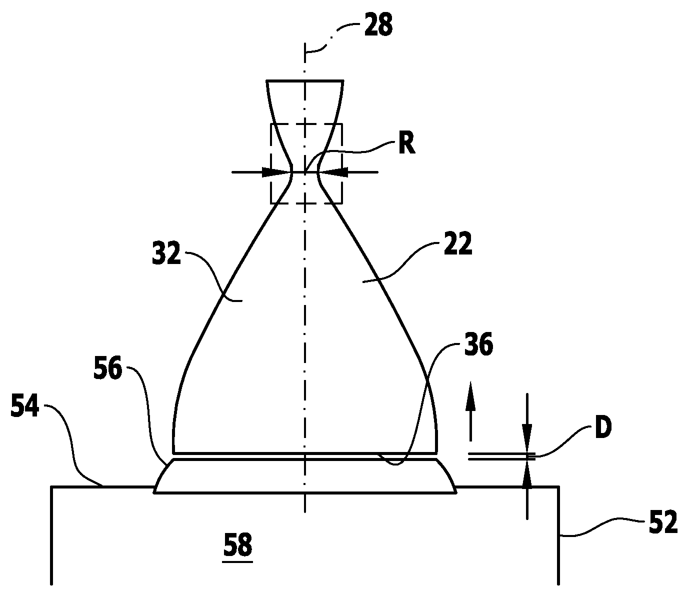
[0048]Arranged on the main body 12 of the flying object 10 is an engine apparatus, designated in its entirety by the reference numeral 22. Said engine apparatus 22 is supplied with fuel from the first tank 18 and oxidizer from the second tank 20.

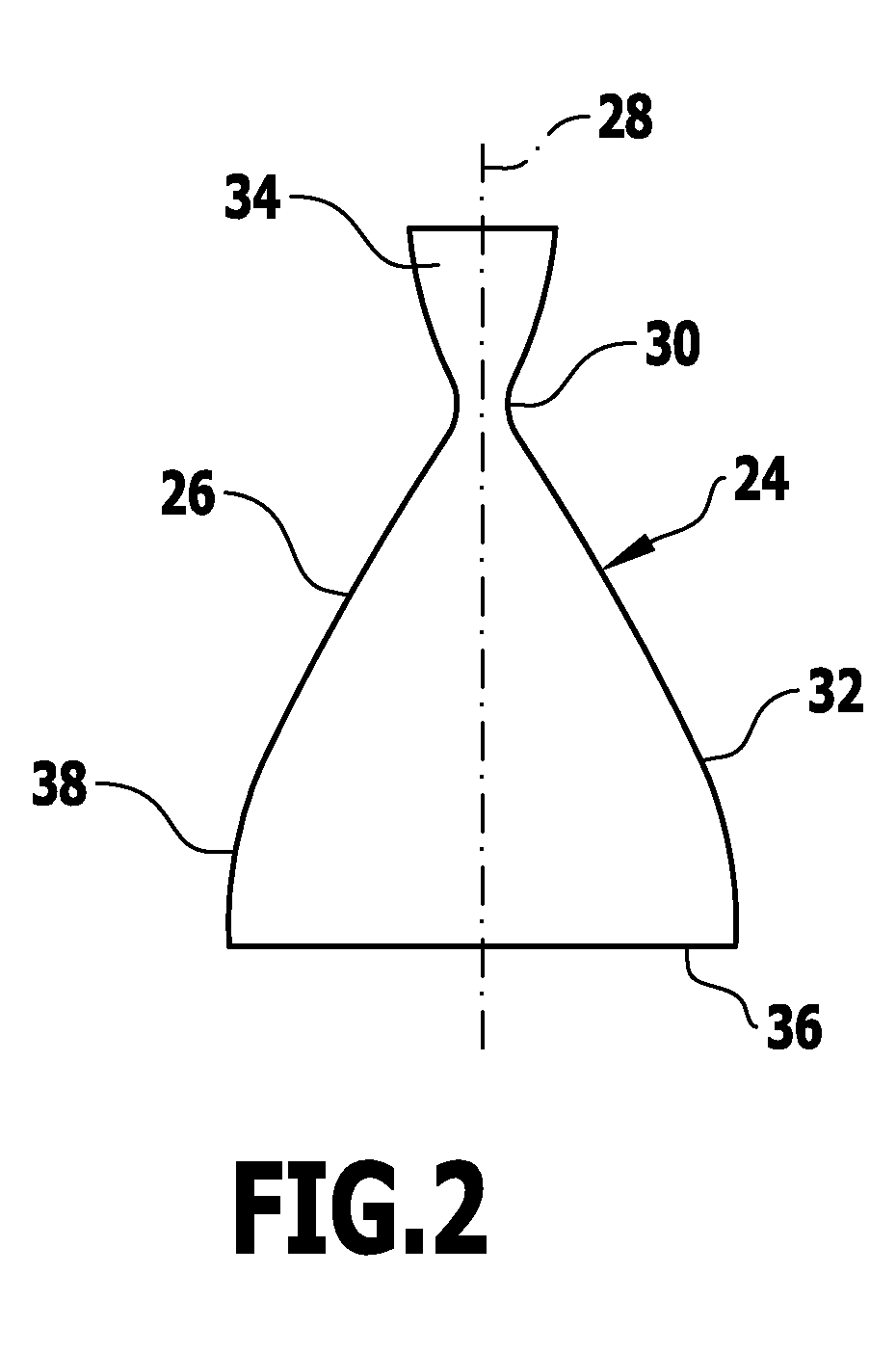
[0049]In principle, the engine apparatus 22 comprises a combustion chamber 24 having a combustion chamber wall designated in its entirety by reference numeral 26. In particular, the combustion chamber 24 is configured to be rotationally symmetric about a combustion chamber axis 28.

[0050]The combustion chamber 24 is configured as a supersonic nozzle ha...


PUM


Abstract

An engine apparatus is provided for a flying object, the engine apparatus including a combustion chamber having a throat region and a nozzle region, the nozzle region having a nozzle wall, wherein the nozzle region expands from the throat region towards an exit end relative to a combustion chamber axis, wherein the nozzle region has associated therewith a skirt having a skirt wall, the skirt being positioned downstream relative to the exit end and surrounding the exit end of the nozzle region, and wherein the skirt wall is at an acute angle away from the combustion chamber axis with respect to the nozzle wall, at least at the exit end of the nozzle region.

Description

CROSS-REFERENCE TO RELATED APPLICATIONS[0001]The present application is a continuation of international application number PCT / EP2011 / 068508, filed on Oct. 24, 2011, which claims priority to German patent application number 10 2010 042 890.6, filed on Oct. 25, 2010, the entire specification of both being incorporated herein by reference in their entirety and for all purposes.BACKGROUND OF THE INVENTION[0002]The invention relates to an engine apparatus for a flying object, comprising a combustion chamber having a throat region and a nozzle region, said nozzle region having a nozzle wall, wherein the nozzle region expands from the throat region towards an exit end of the nozzle region relative to a combustion chamber axis.[0003]The invention further relates to a flying object.[0004]Furthermore, the invention relates to a test stand or a launching ramp for a flying object.[0005]Furthermore, the invention relates to a method for reducing a side load in an engine apparatus, particularly ...

Claims


Application Information

Patent Timeline
Patent Type & Authority Patents(United States)
IPC IPC(8): F02K1/00F02G1/00B64D33/04B63H11/00B64G1/00B64G1/40B64G5/00F02K9/97
CPCF02K9/97B64G1/401B64G1/002B64G5/00
Inventor STARK, RALFGENIN, CHLOE
Owner DEUTSCHES ZENTRUM FUER LUFT & RAUMFAHRT EV
Why Eureka
Try Eureka