

Driven Vane Compressor
a compressor and driven technology, applied in the direction of machines/engines, rotary/oscillating piston pump components, liquid fuel engines, etc., can solve the problems of increased fluid flow pressure loss in the inlet and outlet region, affecting the operation affecting the efficiency of such machines, so as to reduce the side load acting, less power consumption, and longer life
- Summary
- Abstract
- Description
- Claims
- Application Information
AI Technical Summary
Benefits of technology
Problems solved by technology
Method used
Image

Examples
Embodiment Construction
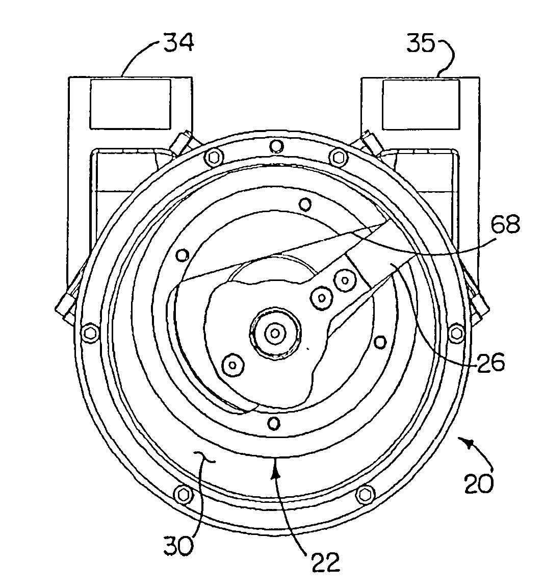
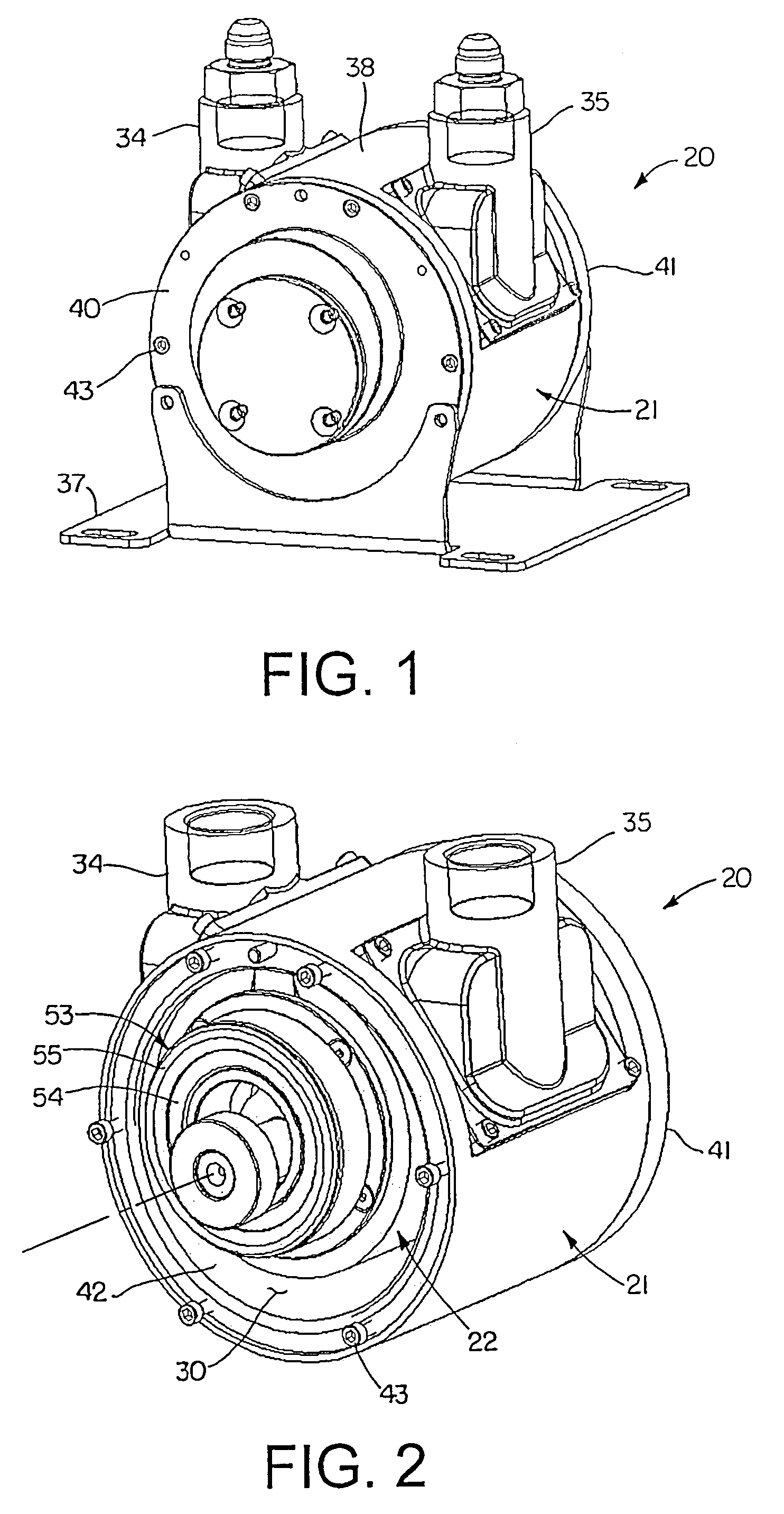
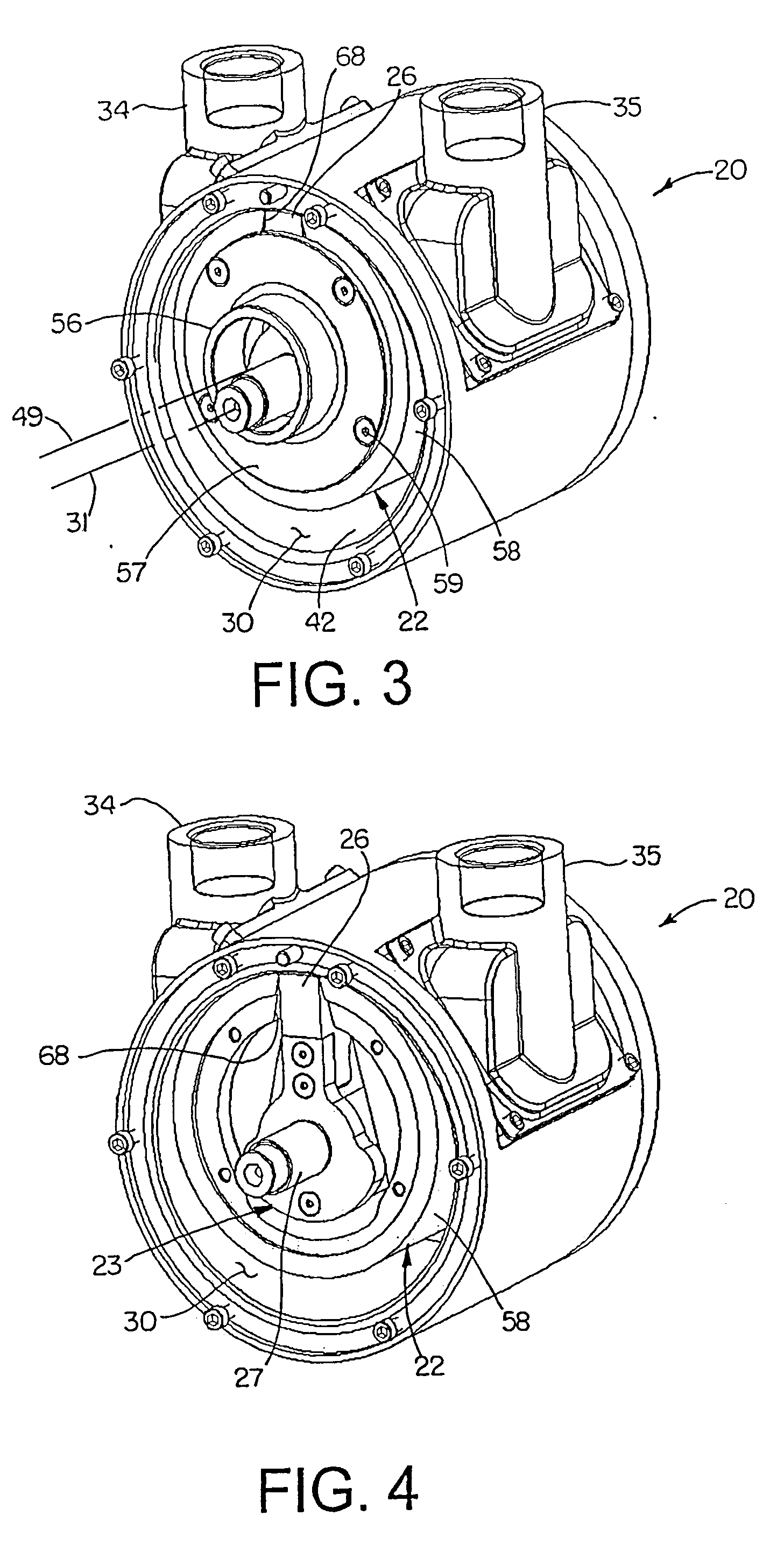
[0027]Referring now to the drawings in detail, and initially to FIGS. 1-5, an exemplary rotary vane device according to the invention is designated generally by reference numeral 20. As shown, the device 20 generally comprises a housing 21, a rotor 22 (FIGS. 3 and 4) and a vane and drive assembly 23 (FIGS. 4 and 6). In the illustrated embodiment, the vane and drive assembly 23, as best seen in FIG. 6, comprises a single vane 26 mounted, or formed integrally with, a vane drive member 27. Although these components will be described below in greater detail, it will be appreciated that such components can vary in various respects without deviating from the basic principles of the present invention. In addition, the illustrated rotary vane device is particularly suited for use as a gas compressor and will be chiefly described in this context. A rotary vane device according to the invention, however, may be adapted for use with other fluids, in particular as a pump for liquids. Additional...
PUM
 Abstract
Description
Claims
Application Information