Method for reducing the nonsteady side loads acting on a nozzle of a rocket engine

a technology of non-steady side loads and rocket engines, which is applied in the direction of marine propulsion, vessel construction, aircraft navigation control, etc., can solve the problems of excessive random pressure distribution in the divergent portion, harmful non-steady side loads, and reduce the overall performance of the engine and its thrust/weight ratio, so as to improve the control of the jet separation and reduce the effect of non-steady loads

Inactive Publication Date: 2009-10-20
EUROPEAN SPACE AGENCY
View PDF6 Cites 4 Cited by
  • Summary
  • Abstract
  • Description
  • Claims
  • Application Information

AI Technical Summary

Benefits of technology

[0014]One object of the invention is to obtain improved control of the jet separation during the startup phase of a rocket engine, and thus to reduce the nonsteady loads acting on the divergent portion of the nozzle.
[0015]Another object of the invention is to obtain such control without increasing the weight of the nozzle or of the rocket.
[0018]A further object of the invention is, through improved control of the jet separation, to improve the overall performance of the rocket engine by lightening its structure and by increasing its expansion ratio.
[0019]At least one of these objects is achieved by a method for reducing the nonsteady side loads acting on a nozzle of a rocket engine during a startup phase of said engine, said nozzle comprising a combustion chamber where exhaust gases are generated, a divergent portion in which a supersonic flow of said exhaust gases occurs, and a throat connecting said combustion chamber to said divergent portion, characterized in that it comprises the positioning of a body of rounded shape inside the divergent portion along its axis corresponding to an axial position of the body of rounded shape such that, during at least part of said startup phase, a shock wave, induced by the disturbance of the flow of the exhaust gases by said body of rounded shape, is incident to the wall of said divergent portion at an axial incidence position where it produces a jet separation or a separation in the form of a toroidal separation bulb.

Problems solved by technology

For other nozzle geometries, or with other expansion ratio conditions for the same nozzle, a different separation mode may occur, called separation mode by internal recirculation in the jet, and which also generates harmful nonsteady side loads.
The need to maintain the nonsteady loads induced by the jet separation at an acceptable level requires limiting the value of the expansion ratio ps / pe to below its optimal value and overdimensioning the nozzle structure, thereby reducing the overall performance of the engine and its thrust / weight ratio.
Despite these precautions, the nonsteady loads generated by the jet separation cause considerable vibrations that are liable to damage the nozzle and even to cause it to break if, with the passage of time, the random pressure distribution in the divergent portion becomes excessively unfavorable.
However, none of the devices described therein is suitable for limiting the appearance of nonsteady side loads while the stagnation pressure in the engine combustion chamber has not yet reached its nominal value, that is, even before the liftoff of the rocket, during the engine startup phase.
During this phase, which lasts about one second or slightly less, the stagnation pressure ps of the gases in the combustion chamber increases rapidly from atmospheric to a peak value and, in consequence, the mean position of the jet separation line shifts toward the nozzle exit section, making ineffective the known control means of the prior art, of which the geometric definition is fixed with respect to the nozzle.
Furthermore, these documents propose the use of devices which are integral with the nozzle during at least part of the ascent phase of the rocket, and which thereby increase its weight, which is contrary to one of the goals of controlling the jet separation, which is to lighten the nozzle by reducing the loads to which it is subjected.
Such a system causes an overall reduction of the nonsteady side loads in the nozzle and has the advantage of being mounted on a ground installation and not carried by the rocket itself, but it is not fully satisfactory because it does not effectively stabilize the jet separation throughout the engine startup phase, since the countercurrent jets impact the nozzle at positions that are fixed and independent of the pressure in the combustion chamber.
In fact, these lines have a stable position at the impact point of the countercurrent fluid jet that initiates them, but can fluctuate downstream of this point, thereby inducing residual nonsteady loads.
This is particularly undesirable because these residual loads are applied correspondingly from the edge of the nozzle exit section, that is, at the place where they are most detrimental, because their moment with respect to the nozzle throat is at maximum.

Method used


Image

  • Method for reducing the nonsteady side loads acting on a nozzle of a rocket engine
  • Method for reducing the nonsteady side loads acting on a nozzle of a rocket engine
  • Method for reducing the nonsteady side loads acting on a nozzle of a rocket engine

Examples


Embodiment Construction

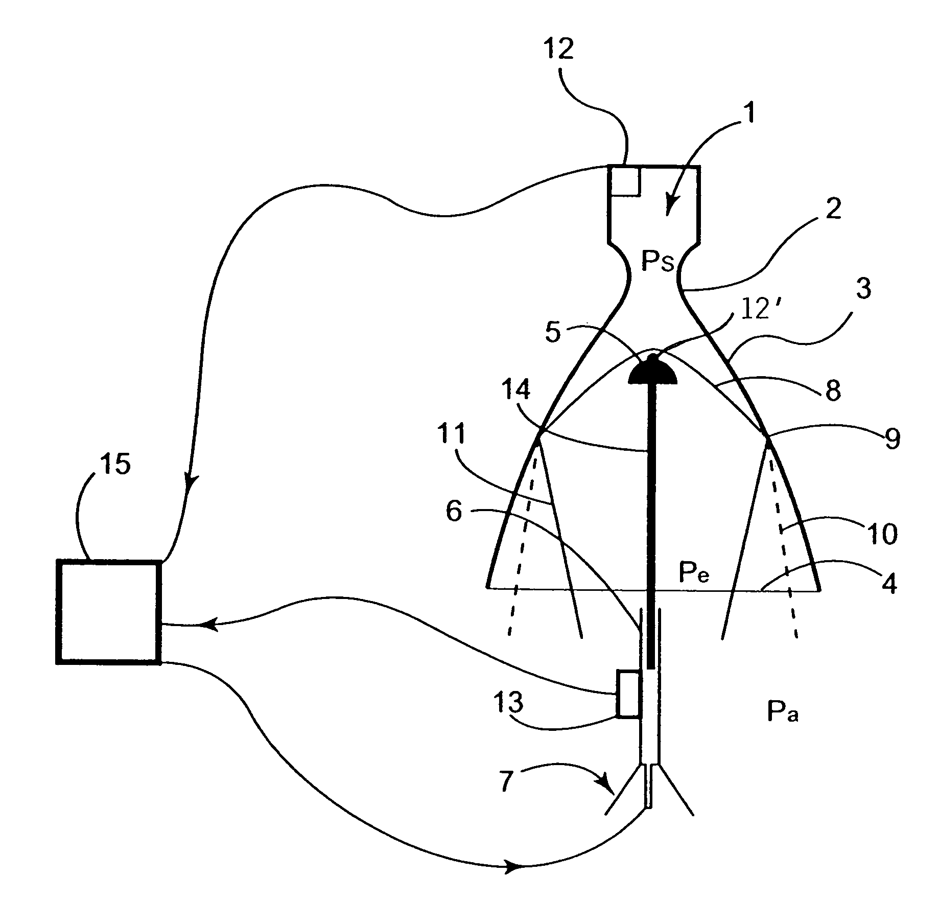
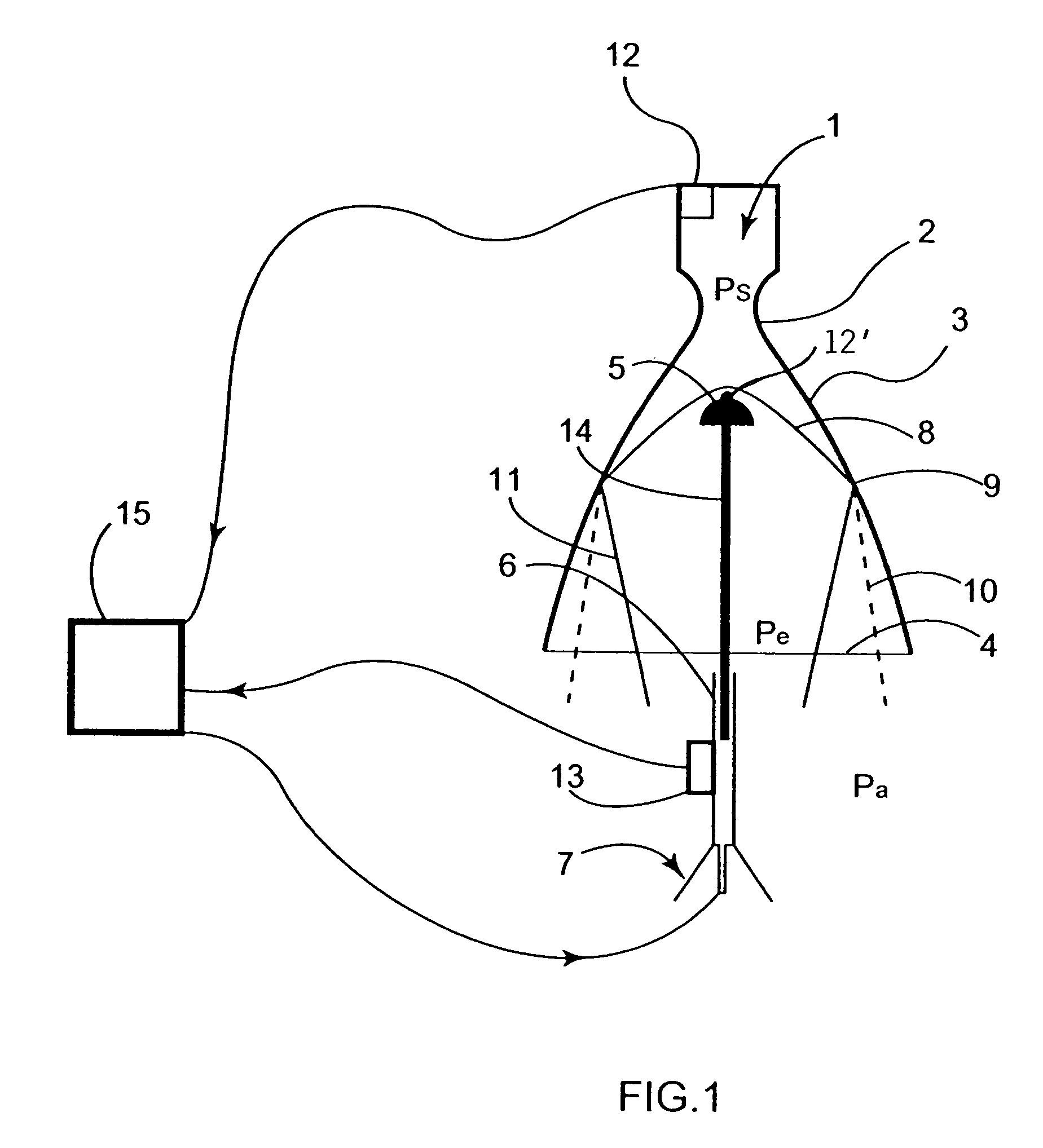
[0050]A rocket engine comprises a combustion chamber 1 in which high temperature and high pressure gases are generated (stagnation pressure ps), and a nozzle comprising: a convergent portion connected to said combustion chamber 1, a throat 2 in which the flow of said gases reaches transonic conditions and a divergent portion 3 in which said flow undergoes expansion and acceleration to supersonic speed. The exit section 4 of the divergent portion terminates outside the engine, in an environment where an external pressure pa prevails, which is about 1 atmosphere at the launch altitude and decreases during the ascension of the rocket to a negligible value when the rocket exits the earth's atmosphere.

[0051]In the rest of the description:[0052]x is the distance between any point of the divergent portion 3 and the throat 2, measured along the nozzle axis;[0053]A(x) is the effective aerodynamic area of the cross section of the nozzle at a distance x from the throat; the aerodynamic area is...


PUM


Abstract

A method for reducing the nonsteady side loads acting on a nozzle of a rocket engine during a startup phase of said engine. The nozzle comprises a combustion chamber (1) where exhaust gases are generated, a divergent portion (3) in which a supersonic flow of said exhaust gases occurs, and a throat (2) connecting the combustion chamber to the divergent portion, which method comprises the positioning of a body of rounded shape (5) inside the divergent portion (3) along its axis corresponding to an axial position such that, during at least part of the startup phase, a shock wave (8), induced by the distrubance of the flow of the exhaust gases by the body of rounded shape (5) is incident to the wall of the divergent portion (3) at an axial incidence position where it produces a jet separation or a separation in the form of a toroidal separation bulb.

Description

FIELD AND BACKGROUND OF THE INVENTION[0001]The invention relates to a device and method for reducing the nonsteady side loads acting on a nozzle of a rocket engine, particularly during the startup or ignition phase of said engine.[0002]The invention can be used in particular to eliminate, or at least substantially limit, the nonsteady side loads occurring in the nozzle of a rocket engine during the ignition thereof, caused by the effect known as jet separation, or the separation of the boundary layer, or a separation by internal recirculation in the jet.[0003]It is known that the thrust of a rocket engine depends on its mass flow rate, on the stagnation pressure ps in the combustion chamber, on the nozzle expansion ratio, that is, on the ratio ps / pe between the stagnation pressure ps and the static ejection pressure of the gases at the nozzle exit Pe, and on the ambient pressure pa. This thrust reaches a peak, for a given set of chamber operating conditions, when the two pressure va...

Claims


Application Information

Patent Timeline
Patent Type & Authority Patents(United States)
IPC IPC(8): F02K1/00
CPCF02K9/95F05D2260/85
Inventor DUJARRIC, CHRISTIAN
Owner EUROPEAN SPACE AGENCY
Why Eureka
Try Eureka