Method of seismic source monitoring using modeled source signatures with calibration functions

a source signature and calibration function technology, applied in seismic signal recording, seismic surveillance, geological measurements, etc., can solve the problems of affecting the accuracy of seismic data acquisition

Active Publication Date: 2007-05-15
PGS EXPLORATION US
View PDF16 Cites 55 Cited by
  • Summary
  • Abstract
  • Description
  • Claims
  • Application Information

AI Technical Summary

Problems solved by technology

The ghost interferes with the direct wave to complicate the source signature.
Although modem airguns produce stable wavefields in a laboratory situation, the wavefields produced by arrays of airguns deployed at sea are not so stable.
In these situations, very small differences in seismic data sets may otherwise be swamped by the source variations.
Shot to shot variations in marine seismic sources are not often monitored, primarily because it is difficult to do.
The far-field method, however, is unreliable because the position of the sensor drifts, only a single point in the wavefield is measured, and it is difficult to position the sensor (hydrophone) the required distance from the source.
Thus, the far-field method is difficult and expensive to do.
However, continuous recording of the near-field signatures is required to recompute the wavefield if the radiation of the airgun array changes or becomes unstable.
The notional source method, however, has some intrinsic practical difficulties.

Method used


Image

  • Method of seismic source monitoring using modeled source signatures with calibration functions
  • Method of seismic source monitoring using modeled source signatures with calibration functions
  • Method of seismic source monitoring using modeled source signatures with calibration functions

Examples


Embodiment Construction

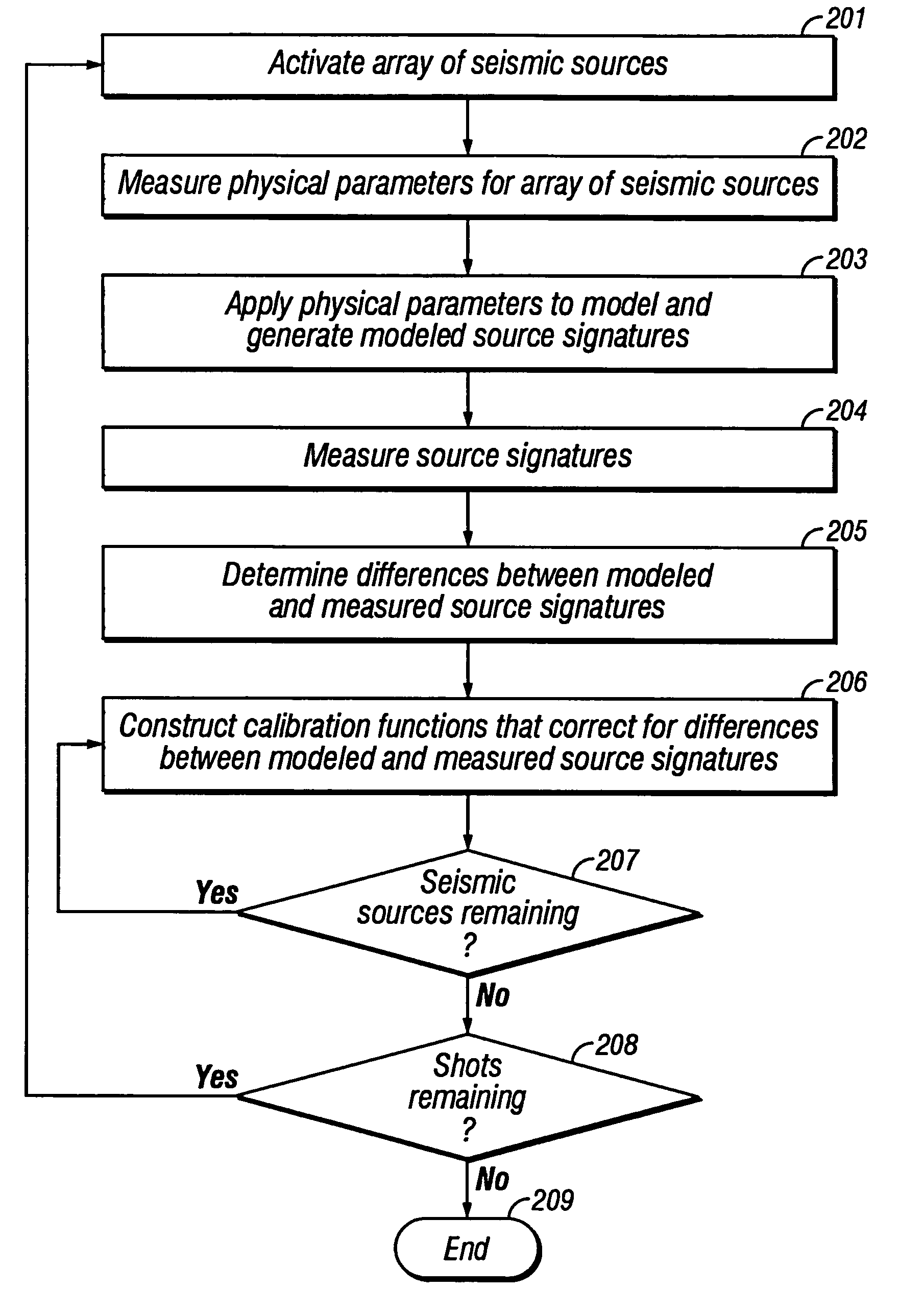
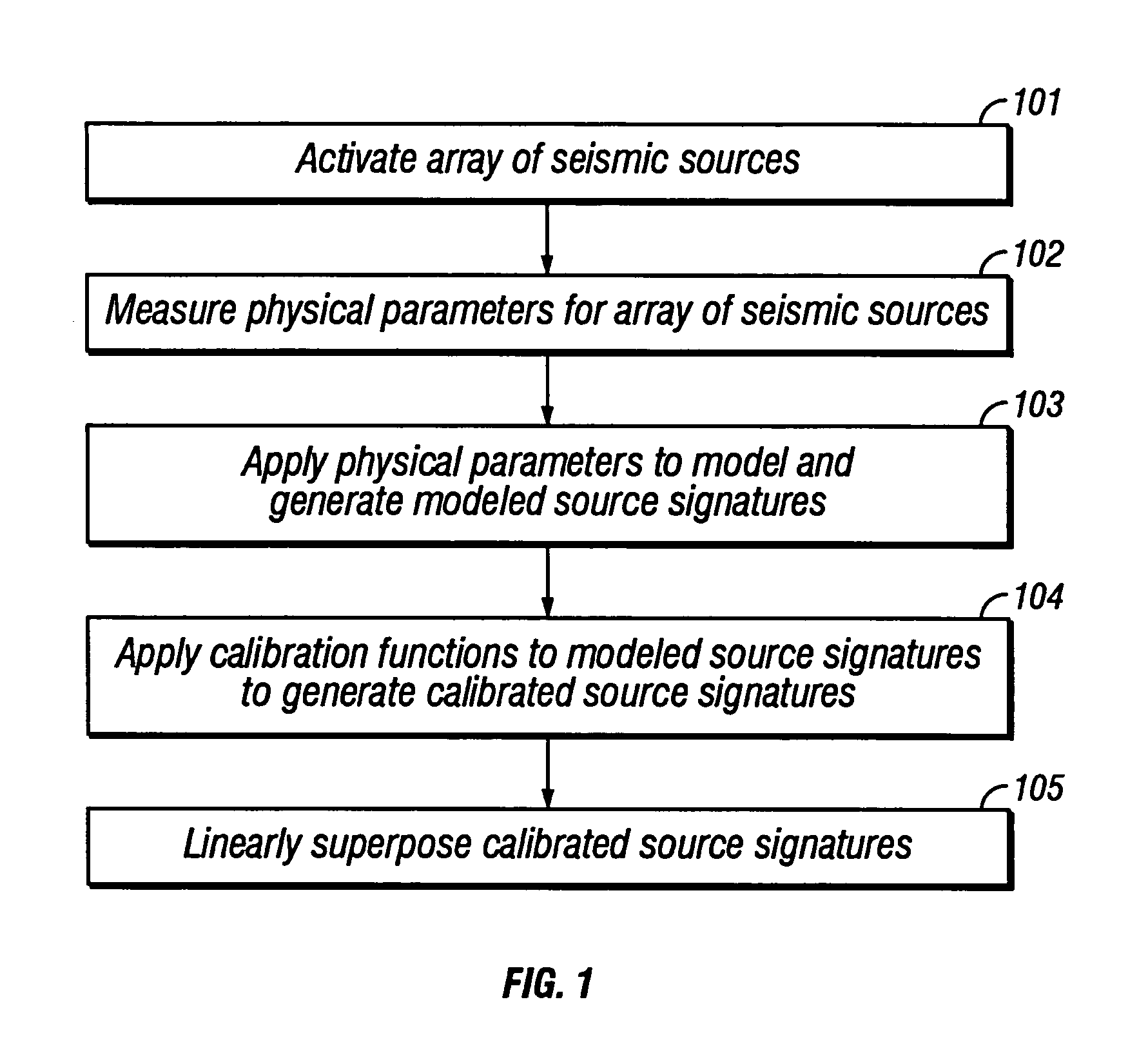
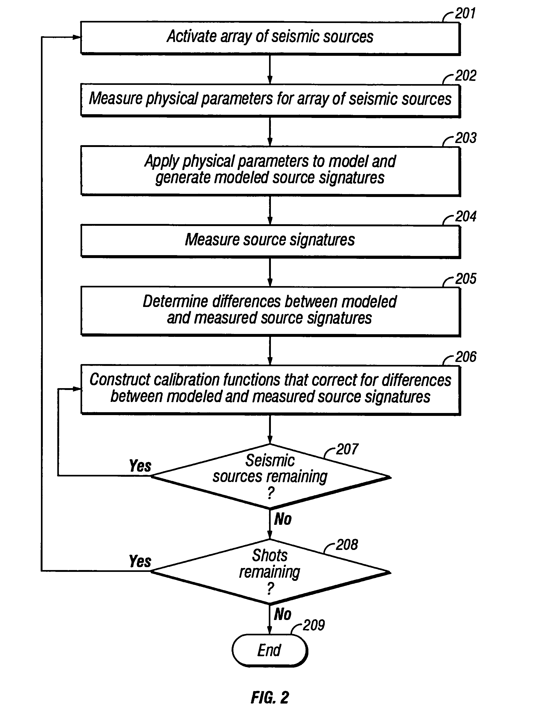
[0040]The invention is a method of seismic source monitoring for an array of seismic sources. The invention makes use of measurements of physical parameters which affect the wavefield generated by the array, a computer model to estimate a source signature for the array from the physical parameter measurements, and calibration functions to improve the estimate of the source signature from the model. The method of the invention produces a source signature which is a continuous function of distance and direction. Thus, the term “source signature”, when utilized with reference to the method of the invention, will designate a three-dimensional wavefield rather than a conventional one-dimensional source signature.

[0041]In one embodiment of the invention, measurements are made of physical parameters for an activation of the array of seismic sources. These measurements of physical parameters are applied to a computer model that outputs an estimate of a source signature for the array of seis...


PUM


Abstract

Physical parameters are measured for an array of seismic sources, preferably for each activation of the seismic sources. Calibration functions are obtained and the measured physical parameters and calibration functions are applied to a model, which generates a calibrated source signature for the array of seismic sources. Alternatively, the measured physical parameters are applied to a model, which generates a modeled source signature, and then the calibration functions are applied to the modeled source signature to generate the calibrated source signature. Alternatively, modeled source signatures are generated for each seismic source and then the calibration functions are applied to the modeled source signatures to generate a calibrated source signature for each seismic source. Then the calibrated source signatures for each seismic source are combined, preferably by linear superposition, to generate the calibrated source signature for the array of seismic sources.

Description

CROSS-REFERENCES TO RELATED APPLICATIONS[0001]Not ApplicableFEDERALLY SPONSOR RESEARCH OR DEVELOPMENT[0002]Not ApplicableSEQUENCE LISTING, TABLE, OR COMPUTER LISTING[0003]Not ApplicableBACKGROUND OF THE INVENTION[0004]1. Field of the Invention[0005]This invention relates generally to the field of geophysical prospecting. More particularly, the invention relates to the field of seismic data acquisition. Specifically, the invention is a method of seismic source monitoring using modeled source signatures with calibration functions.[0006]2. Description of the Related Art[0007]Marine seismic exploration typically employs a submerged seismic source towed by a ship and periodically activated to generate an acoustic wavefield (a “shot”). The wavefield may be generated by a small explosive charge, an electric spark or arc, a vibrator, or, typically, a gun. The gun may be a water gun, vapor gun, or, most typically, an airgun. Each airgun contains a volume of air typically compressed to about ...

Claims


Application Information

Patent Timeline
Patent Type & Authority Patents(United States)
IPC IPC(8): G01V1/38E21B47/14G01VG01V1/02G01V1/28G01V1/36G01V13/00G06F17/00G06F19/00
CPCG01V1/006G01V1/3861G01V13/00G01V1/38G16Z99/00G01V1/28G06F17/00G01V1/26
Inventor PARKES, GREGORY ERNEST
Owner PGS EXPLORATION US
Why Eureka
Try Eureka