
Wake tower and method of making same

a technology of wake tower and boat, which is applied in the field of water sports, can solve the problems of affecting the operation of the boat, affecting the passage of the boat under bridges and other types of overpasses, and affecting the visibility of the operator of the boat, so as to achieve the effect of being ready to mount on the powerboa

Inactive Publication Date: 2007-05-22
TIGE BOATS
View PDF10 Cites 44 Cited by
  • Summary
  • Abstract
  • Description
  • Claims
  • Application Information

AI Technical Summary

Benefits of technology

"The present invention provides a unique wake tower assembly for powerboats that is easy to install and has a unique U-shaped design. The assembly includes a first and second base member that are connected to the gunwale of the boat, a curved structural member with an upper and lower portion, and a bight portion that connects the upper portions. The structural member can be pivoted towards the bow or stern of the boat. The invention also includes a counter-balancing mechanism to resist the movement of the assembly and assist in its return to its upright position. The technical effects of the invention include an improved wake tower assembly that is easy to install and has a unique design that is attractive to powerboats of various constructions."

Problems solved by technology

Such prior art wake towers are heavy and generally quite cumbersome to install and remove from the boat.
Further, such towers may interfere with the boat's passage beneath bridges and other types of overpasses.
Additionally, because of the complexity of the framework of several of the prior art wake towers, visibility of the operator of the boat can be impaired.
However, such prior art structures often have questionable structural stability when erected and can present substantial safety hazards after being disassembled.
For example, after the wake tower structures have been disassembled they can present a substantial tripping hazard to passengers on the boat especially when the boat is being rocked by waves.
Further, in their dismantled configuration, the wake tower structures typically undesirably reduce the usable space on the boat deck.

Method used


Image

  • Wake tower and method of making same
  • Wake tower and method of making same
  • Wake tower and method of making same

Examples


Embodiment Construction

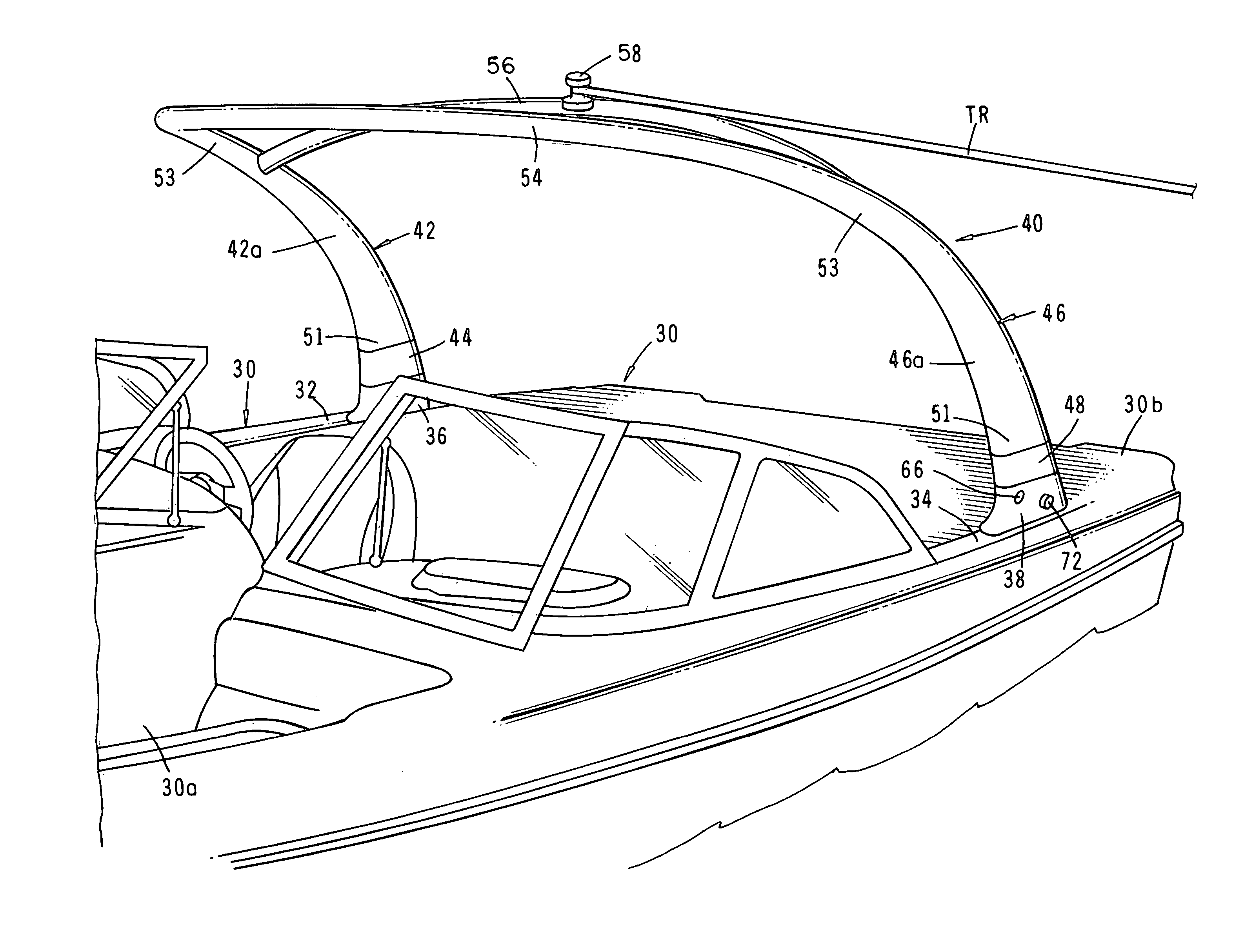
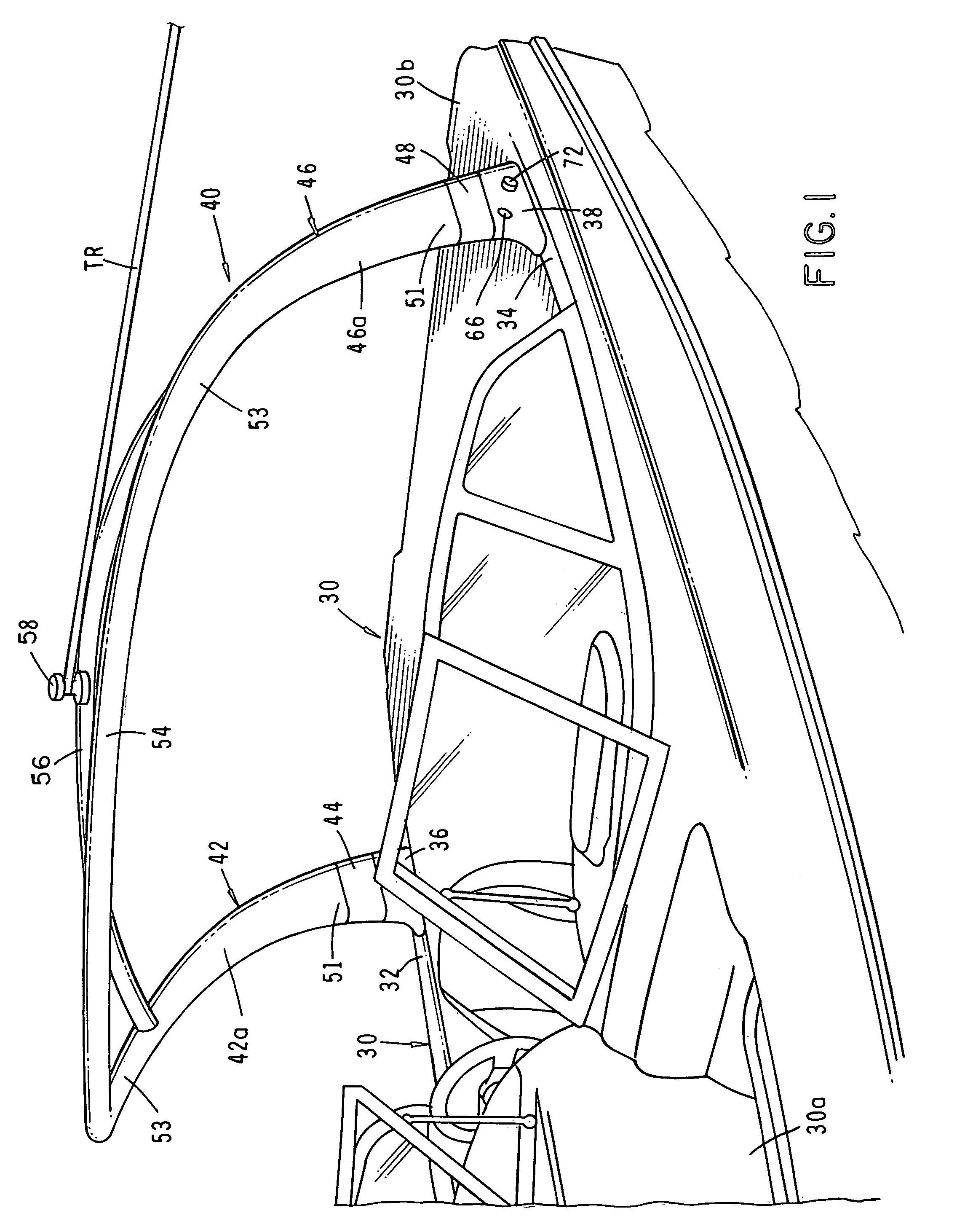
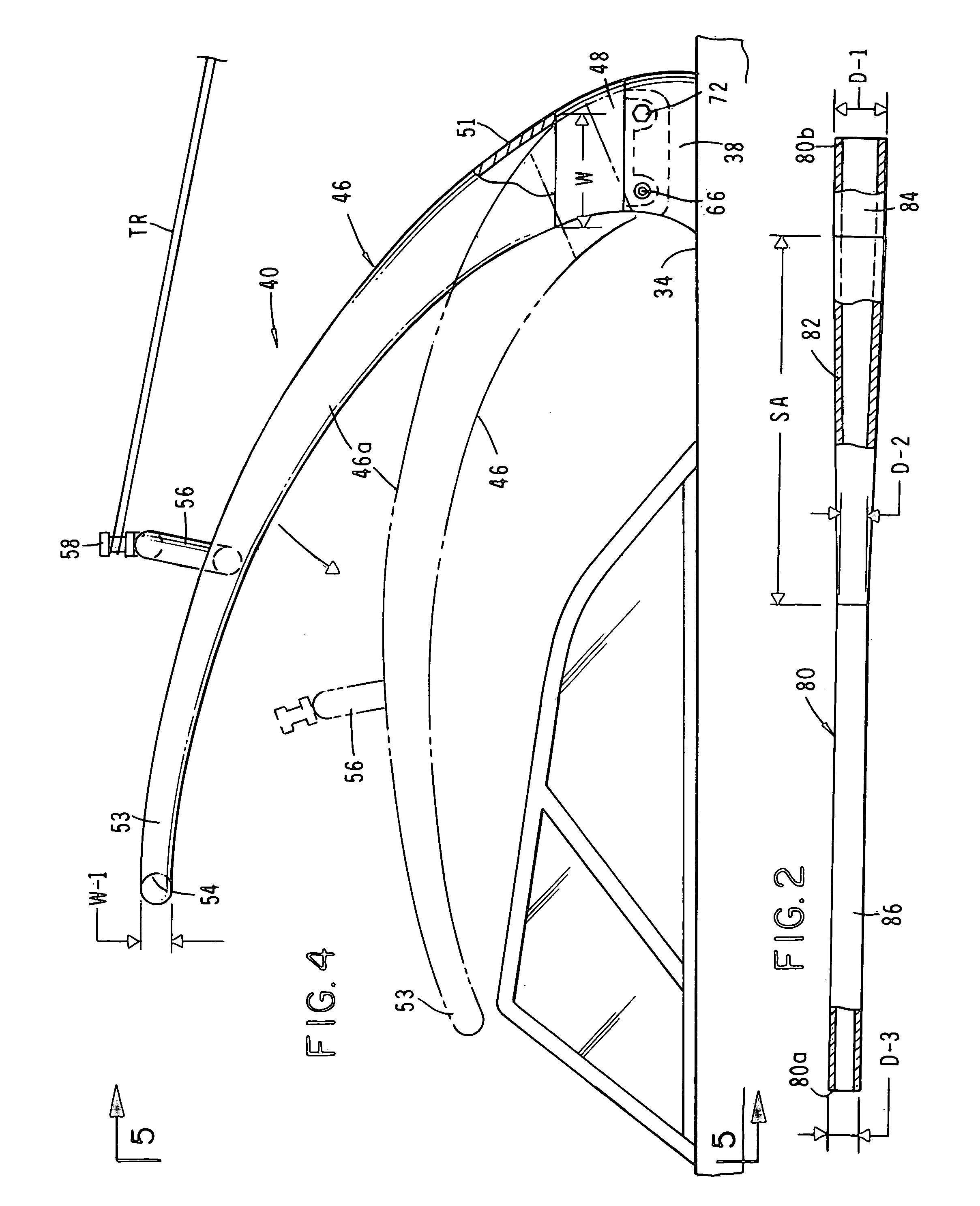
[0079]Referring to the drawings and particularly to FIGS. 1, 4 and 5, one form of the wake tower of the invention is shown interconnected with a powerboat 30 of conventional construction having a bow portion 30a and a stem portion 30b. As best seen in FIG. 5, the powerboat also has first and second spaced-apart gunwales 32 and 34 respectively to which the wake tower is connected. In the present form of the invention the wake tower includes an upwardly extending first base member 36 connected to the first gunwale 32 and an upwardly extending second base member 38 connected to said second gunwale 34. The base members 36 and 38 are of a curved configuration and are preferably cast from a lightweight metal such as aluminum.

[0080]Interconnected with the base members is a generally U-shaped, upwardly extending structural assembly generally designated by the numeral 40. The structural assembly 40 includes a generally “L”-shaped structural member 42 having a first curved side 42a and a cast...


PUM


Abstract

An attractive wake tower assembly of a unique, generally U-Shaped configuration that can be readily pivotally mounted on powerboats of various constructions to enable the wake tower assembly to be pivoted from an upstanding to a lowered position. The wake tower assembly is of a high-strength, simple construction that does not interfere with the visibility of the boat operator. Each of the side members of the assembly has an upper portion and a lower portion, each of which is generally oval in cross section. The lower portion of each of the side members have a first width and the upper portion of each of the side members have a first width; and a bight portion interconnecting the upper portions of the sides, the bight portion being generally circular in cross section.

Description

BACKGROUND OF THE INVENTION[0001]This is a Continuation-In-Part of Application U.S. Ser. No. 10 / 751,218 filed Dec. 31, 2003 now U.S. Pat. No. 6,986,321 which is a Continuation-In-Part of Application U.S. Ser. No. 10 / 401,644 filed Mar. 27, 2003 now U.S. Pat. No. 6,792,888.FIELD OF THE INVENTION[0002]The present invention relates generally to water sports such as wakeboarding. More particularly, the invention concerns a wake tower of novel construction for use with powerboats for towing a performer behind the boat using a tow rope that is connected to the wake tower.DISCUSSION OF THE PRIOR ART[0003]In recent years the sport of wakeboarding has become very popular. As the name implies, the wake boarder intentionally rides the wake of the boat and prefers to have as large a wake as possible generated behind the boat. Experience has shown that, to take full advantage of the wake generated by the boat, it is preferable to anchor the towline used to tow the wake boarder at a relatively hig...

Claims


Application Information

Patent Timeline
Patent Type & Authority Patents(United States)
IPC IPC(8): B63B17/00B63B15/00B63B35/81
CPCB63B15/00B63B17/00B63B17/02B63B35/815B63B34/60
Inventor METCALF, ROBERT
Owner TIGE BOATS
Learn More