Fuel injection device for an internal combustion engine

a fuel injection device and internal combustion engine technology, applied in the direction of fuel injection apparatus, machine/engine, feed system, etc., can solve the problems of increasing the weight and space required contributing to high manufacturing costs, etc., to reduce the space required, weight and cost of the fuel injection system, and reduce the size or simple filter design

Inactive Publication Date: 2007-05-22
ROBERT BOSCH GMBH
View PDF15 Cites 11 Cited by
  • Summary
  • Abstract
  • Description
  • Claims
  • Application Information

AI Technical Summary

Benefits of technology

[0006]The fuel injection system according to the present invention has the advantage over the prior art that the fuel supply pump can be of relatively small dimensions, which makes it possible to minimize the space required, weight, and costs of the fuel injection system. Only when the quantity of fuel delivered by the fuel supply pump is less than the required intake quantity of the high-pressure pump does the high-pressure pump also take in additional fuel from the fuel return. This assures that the high-pressure pump takes in predominantly the cool fuel delivered by the fuel supply pump and only the shortfall is made up by the heated fuel from the fuel return.
[0003]The invention is directed to an improved fuel injection system for an internal combustion engine.
[0006]The fuel injection system according to the present invention has the advantage over the prior art that the fuel supply pump can be of relatively small dimensions, which makes it possible to minimize the space required, weight, and costs of the fuel injection system. Only when the quantity of fuel delivered by the fuel supply pump is less than the required intake quantity of the high-pressure pump does the high-pressure pump also take in additional fuel from the fuel return. This assures that the high-pressure pump takes in predominantly the cool fuel delivered by the fuel supply pump and only the shortfall is made up by the heated fuel from the fuel return.
[0007]Advantageous embodiments and modifications of the fuel injection system according to the present invention are disclosed. One embodiment assures that the high-pressure pump will only take in fuel from the fuel return if the fuel quantity delivered by the fuel supply pump falls short of the required intake quantity. Another embodiment provides for a lubrication and cooling of the drive region of the high-pressure pump while still another assures that the drive region of the high-pressure pump is supplied exclusively with fuel delivered by the fuel supply pump, i.e. cooler fuel. In a further embodiment only the fuel quantity taken in by the high-pressure pump passes through the filter, thus allowing a smaller or simpler filter design to be used.
[0005]A fuel injection system of the type with which this invention is cornered, known from DE 100 02 132 A1, has a high-pressure pump that delivers fuel to an accumulator. A fuel supply pump delivers fuel from a fuel tank to the suction side of the high-pressure pump, and a fuel metering unit between the fuel supply pump and the high-pressure pump can variably adjust the quantity of fuel taken in by the high-pressure pump. The accumulator is connected to at least one injector that injects fuel into the internal combustion engine. A fuel return leads from the injector back to the fuel tank. In order to assure that the high-pressure pump delivers a sufficient supply of fuel to the accumulator in all operating states of the engine, the fuel supply pump must deliver a sufficiently large quantity of fuel to the high-pressure pump. But in order to achieve this, it becomes necessary to provide a fuel supply pump with very large dimensions, which increases the weight and amount of space required of the fuel injection system and also contributes to high manufacturing costs.
[0007]Advantageous embodiments and modifications of the fuel injection system according to the present invention are disclosed. One embodiment assures that the high-pressure pump will only take in fuel from the fuel return if the fuel quantity delivered by the fuel supply pump falls short of the required intake quantity. Another embodiment provides for a lubrication and cooling of the drive region of the high-pressure pump while still another assures that the drive region of the high-pressure pump is supplied exclusively with fuel delivered by the fuel supply pump, i.e. cooler fuel. In a further embodiment only the fuel quantity taken in by the high-pressure pump passes through the filter, thus allowing a smaller or simpler filter design to be used.
[0007]Advantageous embodiments and modifications of the fuel injection system according to the present invention are disclosed. One embodiment assures that the high-pressure pump will only take in fuel from the fuel return if the fuel quantity delivered by the fuel supply pump falls short of the required intake quantity. Another embodiment provides for a lubrication and cooling of the drive region of the high-pressure pump while still another assures that the drive region of the high-pressure pump is supplied exclusively with fuel delivered by the fuel supply pump, i.e. cooler fuel. In a further embodiment only the fuel quantity taken in by the high-pressure pump passes through the filter, thus allowing a smaller or simpler filter design to be used.
[0007]Advantageous embodiments and modifications of the fuel injection system according to the present invention are disclosed. One embodiment assures that the high-pressure pump will only take in fuel from the fuel return if the fuel quantity delivered by the fuel supply pump falls short of the required intake quantity. Another embodiment provides for a lubrication and cooling of the drive region of the high-pressure pump while still another assures that the drive region of the high-pressure pump is supplied exclusively with fuel delivered by the fuel supply pump, i.e. cooler fuel. In a further embodiment only the fuel quantity taken in by the high-pressure pump passes through the filter, thus allowing a smaller or simpler filter design to be used.
[0006]The fuel injection system according to the present invention has the advantage over the prior art that the fuel supply pump can be of relatively small dimensions, which makes it possible to minimize the space required, weight, and costs of the fuel injection system. Only when the quantity of fuel delivered by the fuel supply pump is less than the required intake quantity of the high-pressure pump does the high-pressure pump also take in additional fuel from the fuel return. This assures that the high-pressure pump takes in predominantly the cool fuel delivered by the fuel supply pump and only the shortfall is made up by the heated fuel from the fuel return.
[0007]Advantageous embodiments and modifications of the fuel injection system according to the present invention are disclosed. One embodiment assures that the high-pressure pump will only take in fuel from the fuel return if the fuel quantity delivered by the fuel supply pump falls short of the required intake quantity. Another embodiment provides for a lubrication and cooling of the drive region of the high-pressure pump while still another assures that the drive region of the high-pressure pump is supplied exclusively with fuel delivered by the fuel supply pump, i.e. cooler fuel. In a further embodiment only the fuel quantity taken in by the high-pressure pump passes through the filter, thus allowing a smaller or simpler filter design to be used.

Problems solved by technology

But in order to achieve this, it becomes necessary to provide a fuel supply pump with very large dimensions, which increases the weight and amount of space required of the fuel injection system and also contributes to high manufacturing costs.

Method used


Image

  • Fuel injection device for an internal combustion engine
  • Fuel injection device for an internal combustion engine
  • Fuel injection device for an internal combustion engine

Examples


Embodiment Construction

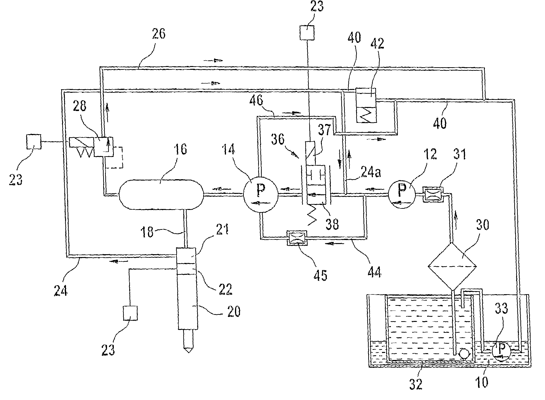
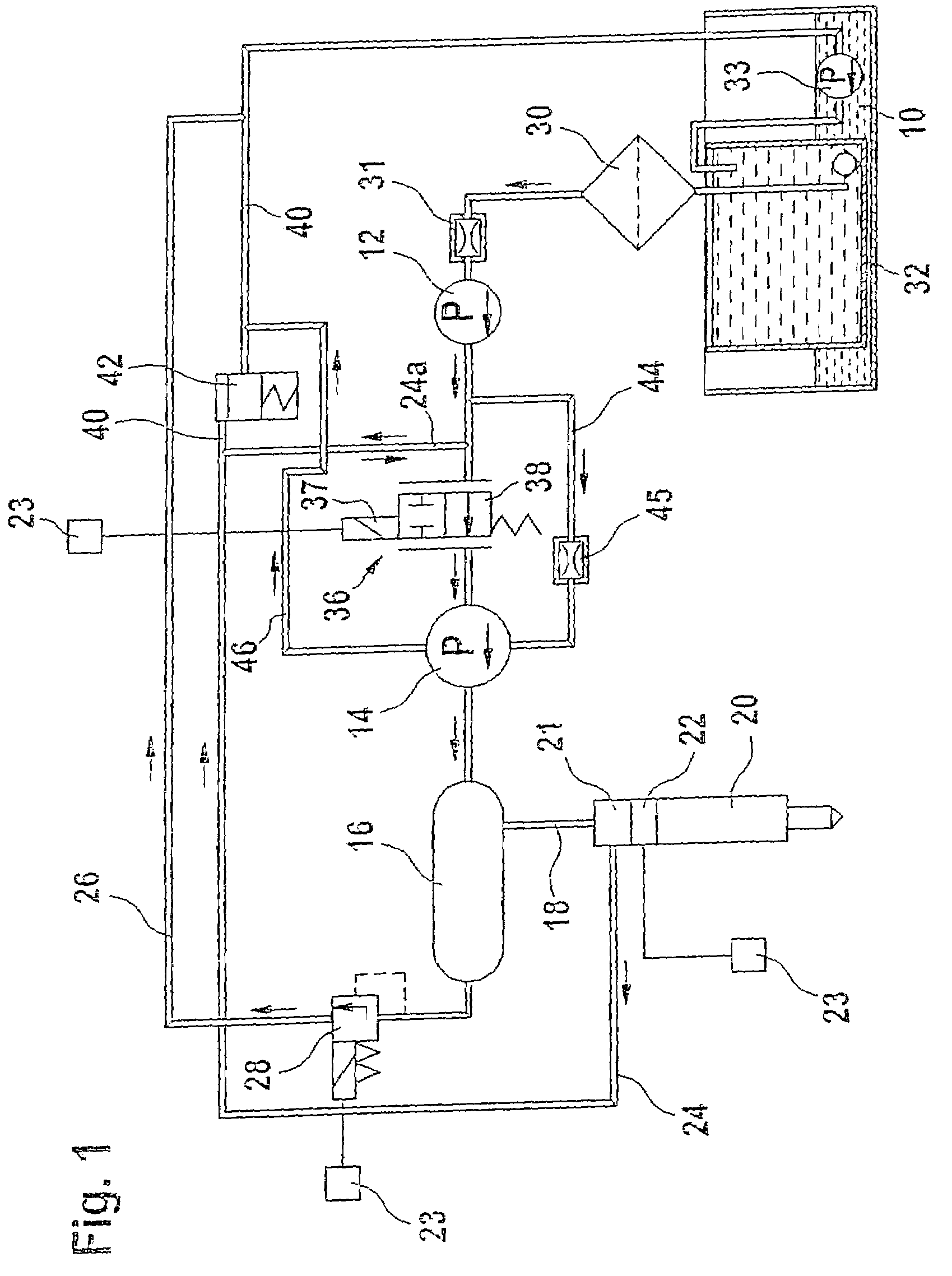
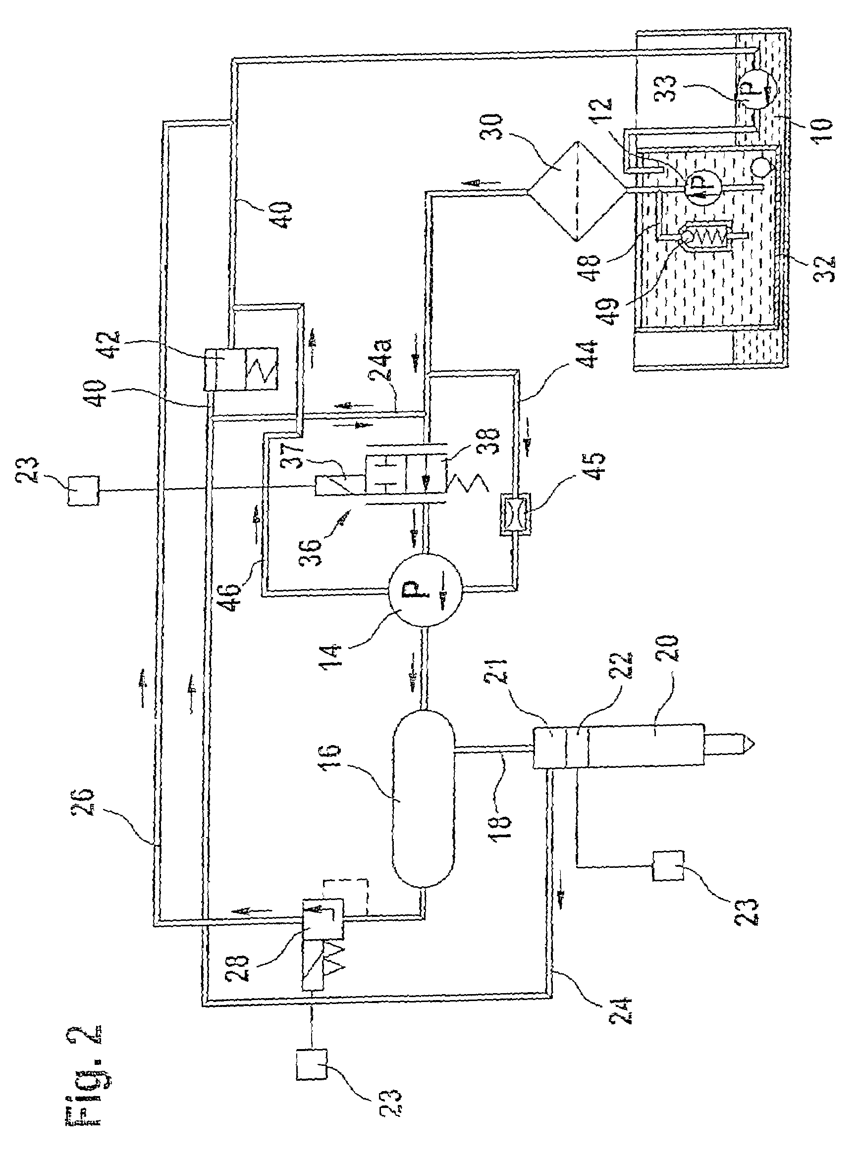
[0012]FIGS. 1 to 3 show a fuel injection system for an internal combustion engine, for example of a motor vehicle. The engine is an autoignition internal combustion engine, for example, and has one or more cylinders. The motor vehicle has a fuel tank 10 that stores fuel for the operation of the engine. The fuel injection system has a fuel supply pump 12 that delivers fuel from the fuel tank 10 to a high-pressure pump 14. The high-pressure pump 14 delivers fuel to an accumulator 16 that can be embodied, for example, in the form of a tube or in any other shape. At least one line 18 leads from the accumulator 16 to at least one injector 20 associated with a cylinder of the engine; preferably, the accumulator 16 is connected to a number of injectors 20. Each of the injectors 20 is provided with an electric control valve 22 that controls at least one opening of the respective injector in order to trigger or prevent a fuel injection through the injector 20. An electronic control unit 23 t...


PUM


Abstract

The fuel injection system has a high-pressure pump that delivers fuel to an accumulator and fuel supply pump delivers fuel to the suction side of the high-pressure pump, with a fuel metering unit between the fuel supply and high-pressure pumps to variably adjust the fuel quantity taken in by the high-pressure pump. The accumulator is connected to at least one fuel injector and a return leads from the fuel injector(s). The fuel return from the injector(s) feeds into the connection between the fuel supply pump and the fuel metering unit. A connection controlled by a pressure valve leads from the fuel return to a discharge region. The high-pressure pump only draws fuel from the fuel return in operating states in which the fuel quantity delivered by the fuel supply pump is less than the required intake quantity of the high-pressure pump.

Description

CROSS-REFERENCE TO RELATED APPLICATIONS[0001]This application is a 35 USC 371 application of PCT / DE 2004 / 001690 filed on Jul. 28, 2004.BACKGROUND OF THE INVENTION[0002]1. Field of the Invention[0003]The invention is directed to an improved fuel injection system for an internal combustion engine.[0004]2. Description of the Prior Art[0005]A fuel injection system of the type with which this invention is cornered, known from DE 100 02 132 A1, has a high-pressure pump that delivers fuel to an accumulator. A fuel supply pump delivers fuel from a fuel tank to the suction side of the high-pressure pump, and a fuel metering unit between the fuel supply pump and the high-pressure pump can variably adjust the quantity of fuel taken in by the high-pressure pump. The accumulator is connected to at least one injector that injects fuel into the internal combustion engine. A fuel return leads from the injector back to the fuel tank. In order to assure that the high-pressure pump delivers a sufficie...

Claims


Application Information

Patent Timeline
Patent Type & Authority Patents(United States)
IPC IPC(8): F02M37/04F02M37/10F02M47/02F02M55/00F02M59/34F02M63/02
CPCF02M37/106F02M47/027F02M55/002F02M59/34F02M63/0225F02M63/025
Inventor LUDWIG, THOMASMENNICKEN, MICHAELKELLNER, ANDREASBOLTZ, JOACHIMBREDOW, FALKO
Owner ROBERT BOSCH GMBH
Why Eureka
Try Eureka