
Fuel injection control device of engine

a control device and engine technology, applied in the direction of electric control, process and machine control, instruments, etc., can solve the problems of increasing combustion noise, affecting the effect of pilot injection on combustion noise reduction, and increasing combustion noise, so as to prevent the increase of combustion noise and degradation of exhaust gas performance, and the effect of reducing the performance of post-treatment devices by increasing the temperatur

Active Publication Date: 2011-02-17
ISUZU MOTORS LTD
View PDF7 Cites 4 Cited by
  • Summary
  • Abstract
  • Description
  • Claims
  • Application Information

AI Technical Summary

Benefits of technology

[0008]Where inter-cylinder correction is performed by the above-described correction A, when pilot injection is performed to reduce combustion noise in a medium- and high-load range of the engine, the fuel injection amount of pilot injection is greatly increased or decreased by the inter-cylinder correction, the effect of combustion noise reduction by pilot injection can be greatly affected, and the combustion noise is increased or exhaust gas performance can deteriorate.
[0010]Accordingly, it is an object of the present invention to provide a fuel injection control device of an engine that can prevent the increase in combustion noise and degradation of exhaust gas performance and also can prevent the decrease in temperature increase performance of the post-treatment device by inhibiting abrupt fluctuations of fuel injection amount in each injection of main injection and sub-injection caused by inter-cylinder correction.
[0016]The effect demonstrated according to the present invention is that the increase in combustion noise and degradation of exhaust gas performance can be prevented and also the decrease in temperature increase performance of the post-treatment device can be also prevented by inhibiting abrupt fluctuations of fuel injection amount in each injection of main injection and sub-injection caused by inter-cylinder correction.

Problems solved by technology

Where inter-cylinder correction is performed by the above-described correction A, when pilot injection is performed to reduce combustion noise in a medium- and high-load range of the engine, the fuel injection amount of pilot injection is greatly increased or decreased by the inter-cylinder correction, the effect of combustion noise reduction by pilot injection can be greatly affected, and the combustion noise is increased or exhaust gas performance can deteriorate.

Method used


Image

  • Fuel injection control device of engine
  • Fuel injection control device of engine
  • Fuel injection control device of engine

Examples


Embodiment Construction

[0019]A preferred embodiment of the present invention will be explained below in greater detail with reference to the appended drawings.

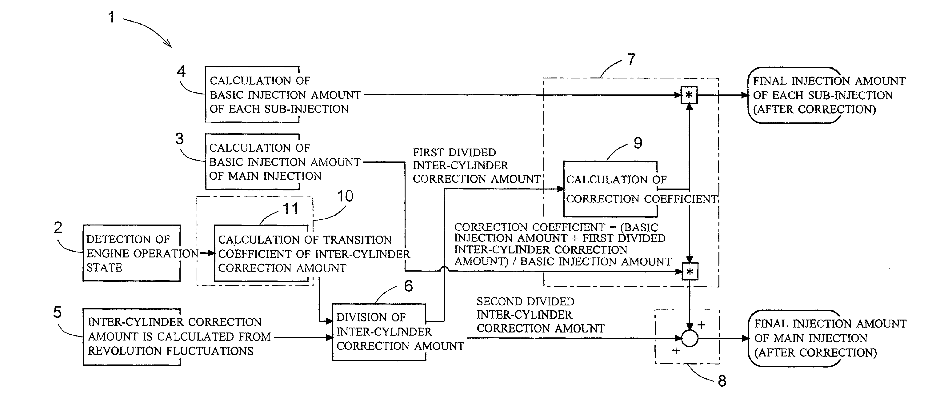
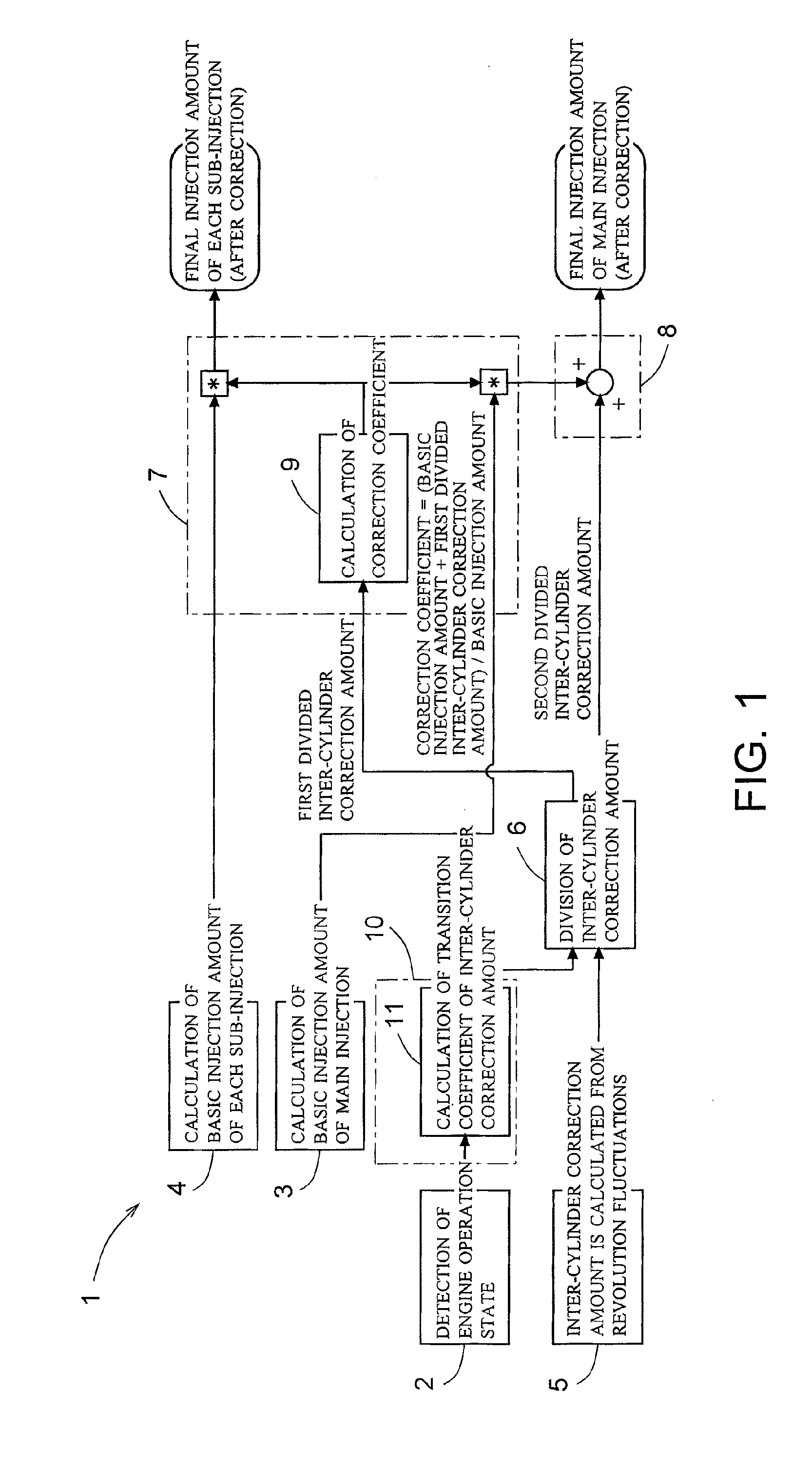
[0020]FIG. 1 is a block diagram illustrating an embodiment of a fuel injection control device for an engine in accordance with the present invention.

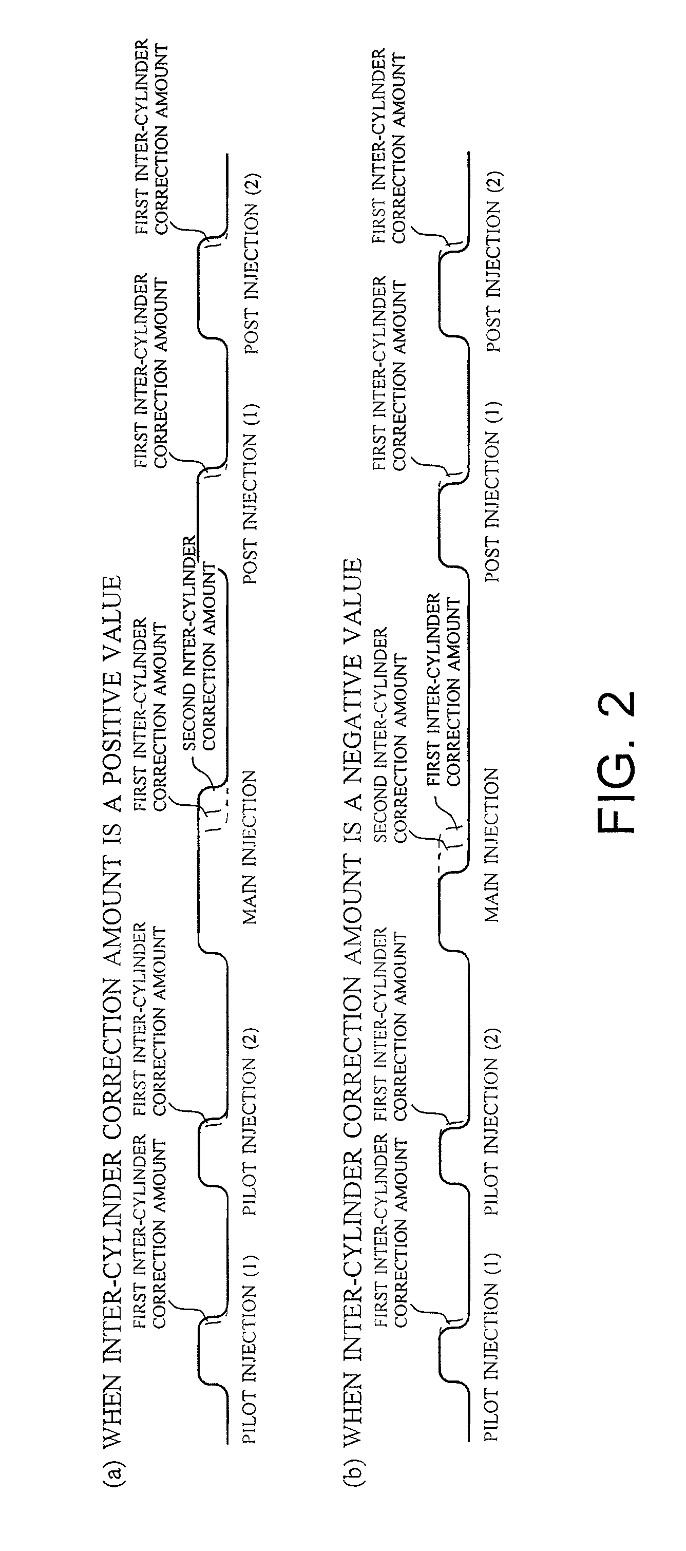
[0021]The engine of the present embodiment is a multicylinder diesel engine having a plurality of cylinders. A fuel injection control device 1 of the present embodiment has a multistage fuel injection mode in which fuel injection by a fuel injection device (injector) is performed in one cycle for each cylinder with a division into a plurality of cycles including main injection, sub-injection (pilot injection) performed before the main injection, and sub-injection (post injection) performed after the main injection (see FIG. 2). The pilot injection in a relatively small amount performed prior to the main injection in a relatively large amount inhibits rapid increase in pressure inside the cylinder and ra...


PUM


Abstract

Increase in combustion noise and deterioration of exhaust gas performance caused by inter-cylinder correction are prevented, and decrease in temperature rise performance of a diesel particulate removal device caused by inter-cylinder correction is prevented. A fuel injection control device of an engine comprises inter-cylinder correction amount calculation means 5 for calculating, for each cylinder, an inter-cylinder correction amount for correcting by increasing / decreasing a fuel injection amount in each cylinder according to a difference in engine revolution speed between the cylinders, inter-cylinder correction amount division means 6 for dividing the inter-cylinder correction amount into a first divided inter-cylinder correction amount for correcting by increasing / decreasing the basic injection amounts of main injection and sub-injection and a second divided inter-cylinder correction amount for correcting by increasing / decreasing only the basic injection amount of main injection, first correction means 7 for distributing the first divided inter-cylinder correction amount to main injection and sub-injection according to the basic injection amount of main injection and sub-injection, and second correction means 8 for adding the second divided inter-cylinder correction amount to the basic injection amount of main injection.

Description

CROSS REFERENCE TO RELATED APPLICATIONS[0001]This application is entitled to the benefit of and incorporates by reference essential subject matter disclosed in International Patent Application No. PCT / JP2009 / 055792 filed on Mar. 24, 2009 and Japanese Patent Application No. 2008-116948 filed Apr. 28, 2008.TECHNICAL FIELD[0002]The present invention relates to a fuel injection control device of an engine which has a plurality of cylinders and in which main injection and sub-injection performed before the main injection or after the main injection are implemented in one cycle for each cylinder.BACKGROUND ART[0003]In an engine having a plurality of cylinders (multicylinder engine) such as a diesel engine, a difference in fuel injection amount between the cylinders can be caused by aging deterioration of fuel injection devices (injectors) provided in the cylinders or individual differences therebetween. The difference in fuel injection amount between the cylinders is demonstrated as fluct...

Claims


Application Information

Patent Timeline
IPC IPC(8): F02D41/26
CPCF02D41/0085Y02T10/44F02D41/402F02D41/1498Y02T10/40
Inventor HIRATANI, YUSUKENAKANO, FUTOSHI
Owner ISUZU MOTORS LTD
Learn More