Particle capturing device regeneration system and control method thereof

A particle capture and regeneration system technology, which is applied in the direction of electric control, electric control, and muffler of exhaust treatment devices, can solve the problems of increasing engine fuel consumption, difficulty in adopting, and increasing difficulty in structural layout, so as to promote regeneration, The effect of reducing fuel consumption

Active Publication Date: 2020-05-19
CHINA FIRST AUTOMOBILE
View PDF9 Cites 4 Cited by
  • Summary
  • Abstract
  • Description
  • Claims
  • Application Information

AI Technical Summary

Problems solved by technology

However, this method requires additional arrangement of air tanks and pipelines, which increases the difficulty of structural layout and is difficult to adopt on the whole vehicle.
The other is to use electric heating to increase the exhaust temperature. For traditional power vehicles, ordinary batteries cannot provide high-voltage current to support the work of electric heaters. This method is only suitable for hybrid vehicles; and in hybrid vehicles, it needs The heating operation of the electric heater is supported by driving the motor to brake and generate electricity, while driving the motor to brake and generate electricity will increase the fuel consumption of the engine, so the power consumption of the electric heater will increase the fuel consumption of the engine, which is not conducive to the economy of the vehicle

Method used


Image

  • Particle capturing device regeneration system and control method thereof
  • Particle capturing device regeneration system and control method thereof
  • Particle capturing device regeneration system and control method thereof

Examples


Embodiment Construction

[0047] In order to make the technical problems solved by the present invention, the technical solutions adopted and the technical effects achieved clearer, the technical solutions of the present invention will be further described below in conjunction with the accompanying drawings and through specific implementation methods.

[0048] In the description of the present invention, unless otherwise clearly specified and limited, the terms "connected", "connected" and "fixed" should be understood in a broad sense, for example, it can be a fixed connection, a detachable connection, or an integrated ; It can be a mechanical connection or an electrical connection; it can be a direct connection or an indirect connection through an intermediary, and it can be the internal communication of two components or the interaction relationship between two components. Those of ordinary skill in the art can understand the specific meanings of the above terms in the present invention in specific si...


PUM


Abstract

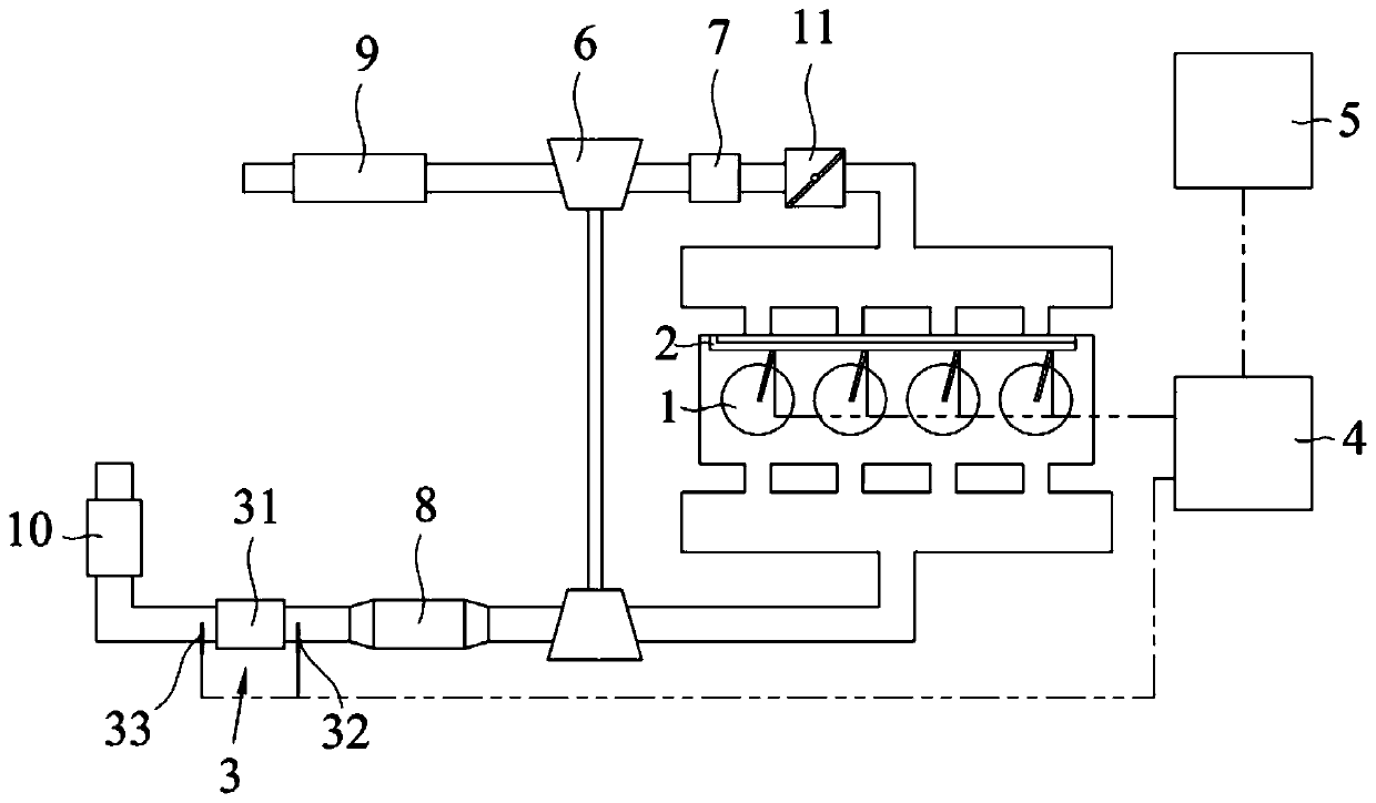
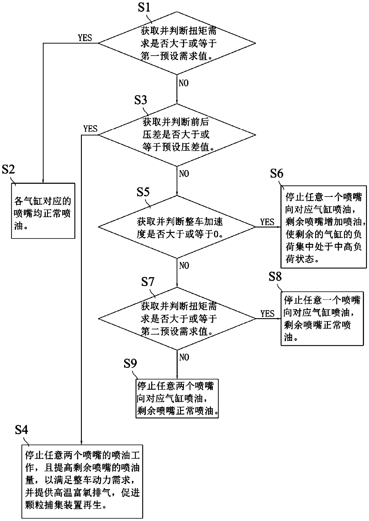
The invention relates to the technical field of automobiles, and discloses a particle capturing device regeneration system and a control method thereof. The particle capturing device regeneration system comprises an engine, a particle capturing device, an ECU and a vehicle controller; the engine comprises an oil injection mechanism and a plurality of air cylinders, air inlets of the air cylinderscommunicate with an air inlet pipeline, and air outlets of the air cylinders communicate with an air outlet pipeline; the oil injection mechanism comprises a plurality of spray nozzles corresponding to all the air cylinders one to one, and all the spray nozzles inject oil towards the corresponding air cylinders; and the ECU is in signal connection with the particle capturing device and the vehiclecontroller and is controllably connected with the oil injection mechanism. The particle capturing device regeneration system and the control method thereof have the advantages that the ECU can selectively control parts of the spray nozzles to stop oil injection according to the front-back differential pressure delta P and a vehicle signal sent by the vehicle controller, the oil injection amount of the remaining spray nozzles can be increased, thus regeneration of the particle capturing device is promoted by increasing the oxygen content of exhausted gas while the vehicle power demand is met,and compared with the situation that regeneration of the particle capturing device is promoted by increasing the temperature of the exhausted gas through electric heating, more oil is saved.

Description

technical field [0001] The invention relates to the technical field of automobiles, in particular to a regeneration system of a particle trapping device and a control method thereof. Background technique [0002] With the increasingly stringent emission and fuel consumption regulations, energy saving and emission reduction has become the primary goal of today's automotive engine development. In order to meet the requirements of particulate matter emission regulations, particulate capture devices have become one of the many mainstream exhaust after-treatment devices. [0003] Existing regeneration systems and control methods of particulate traps can be classified into two types: passive regeneration and active regeneration. Among them, passive regeneration means that the particle trap automatically reaches the regeneration condition under the working conditions such as deceleration and fuel cut-off of the vehicle without external operation. Active regeneration refers to inc...

Claims


Application Information

Patent Timeline
Patent Type & Authority Applications(China)
IPC IPC(8): F01N3/023F01N9/00F01N11/00F02D41/30F02D41/38F02D41/02
CPCF01N3/023F01N9/002F01N11/002F01N2560/08F01N2900/1406F02D41/029F02D41/30F02D41/38Y02T10/40
Inventor 韩令海马赫阳王占峰李金成
Owner CHINA FIRST AUTOMOBILE
Why Eureka
Try Eureka