

System for injecting fuel into a turbomachine
a turbomachine and combustion chamber technology, applied in liquid fuel engines, process and machine control, instruments, etc., can solve the problems of non-uniform fuel injection into the combustion chamber, non-uniform metering valve opening and closing after a delay, and the turbomachine lighting is not uniform, so as to reduce the non-uniform rate, simplify the hydraulic circuit, and reduce the effect of non-uniformity
- Summary
- Abstract
- Description
- Claims
- Application Information
AI Technical Summary
Benefits of technology
Problems solved by technology
Method used
Image

Examples
Embodiment Construction
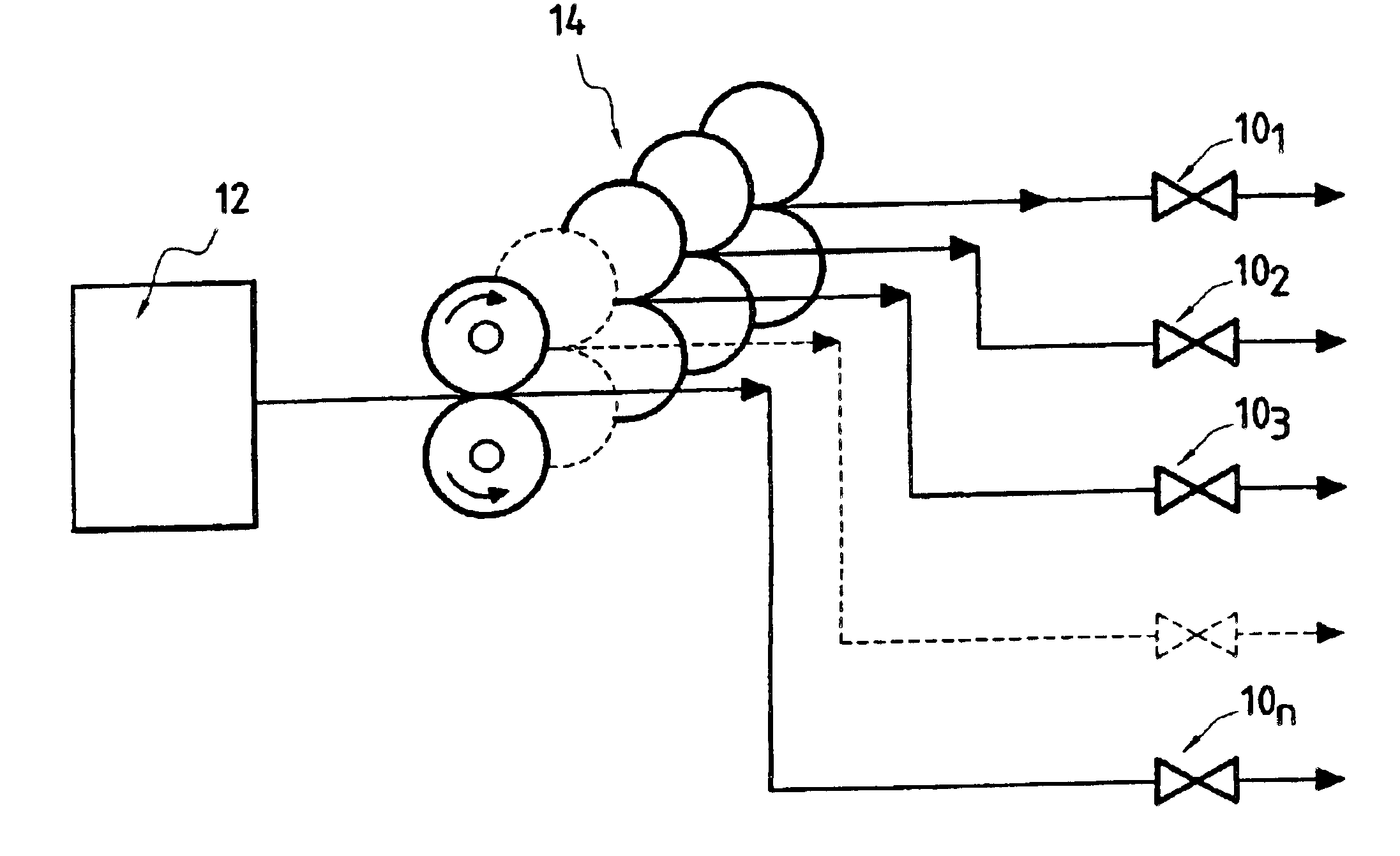
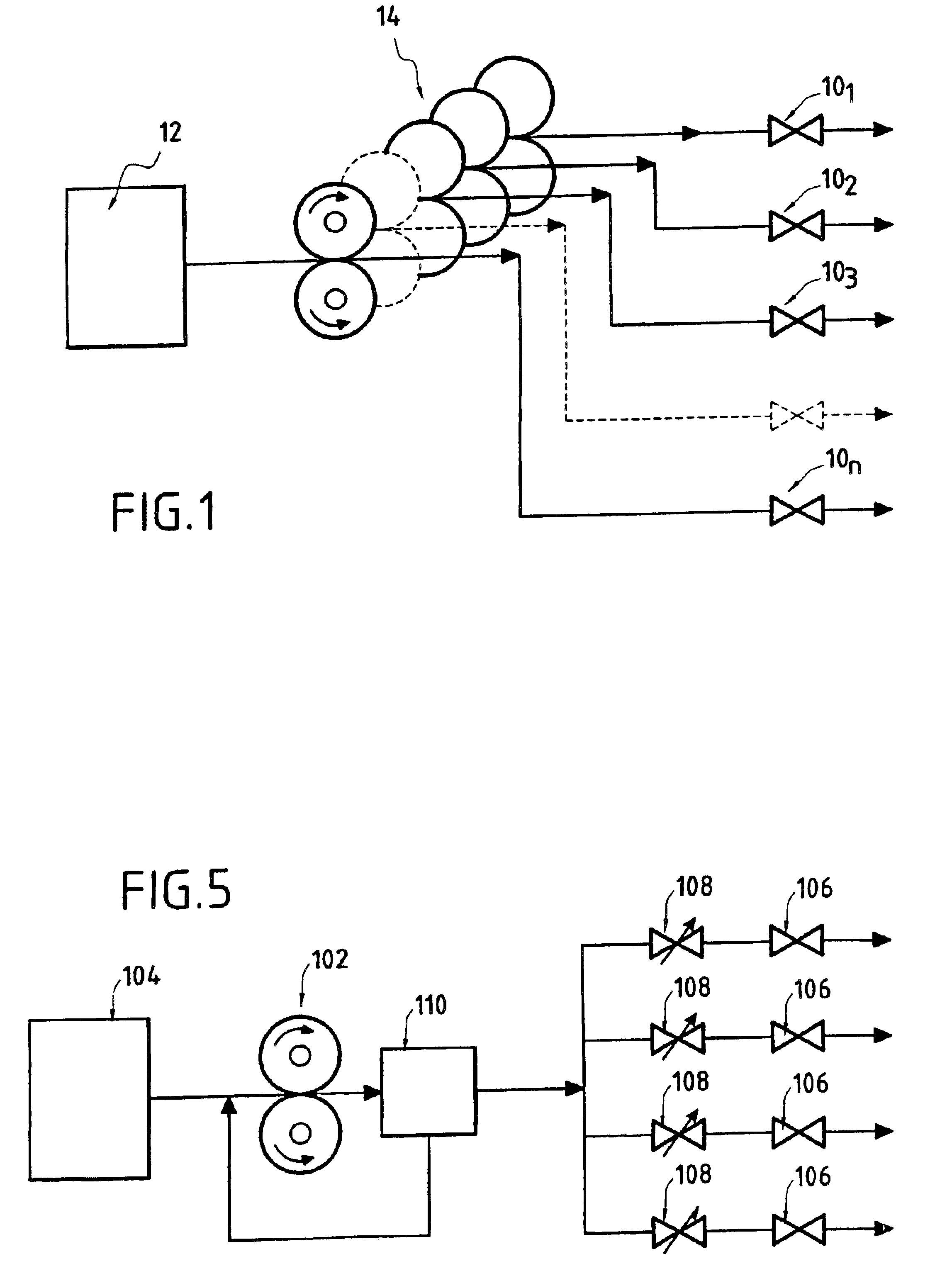
Reference is made initially to FIG. 1 which is a diagram showing the hydraulic circuit of the fuel injection system of the invention.
In this figure, there can be seen a system for injecting fuel into a turbomachine having N injectors 101 to 10N (only four are shown in FIG. 1) disposed in a combustion chamber (not shown) of the turbomachine. The injectors 101 to 10N are fed with fuel from a fuel tank 12. A single pumping means 14 is interposed between the N injectors 101 to 10N and the fuel tank 12 so as to take fuel from the tank and deliver fuel to the injectors in N metered flows that are preferably all at the same rate. In a single action, the single pumping means 14 serves both to pump the fuel from the tank and to deliver the fuel as pumped in this way to the N injectors. The fuel is also delivered in such a manner as to meter the N flow rates delivered to the injectors 101 to 10N.
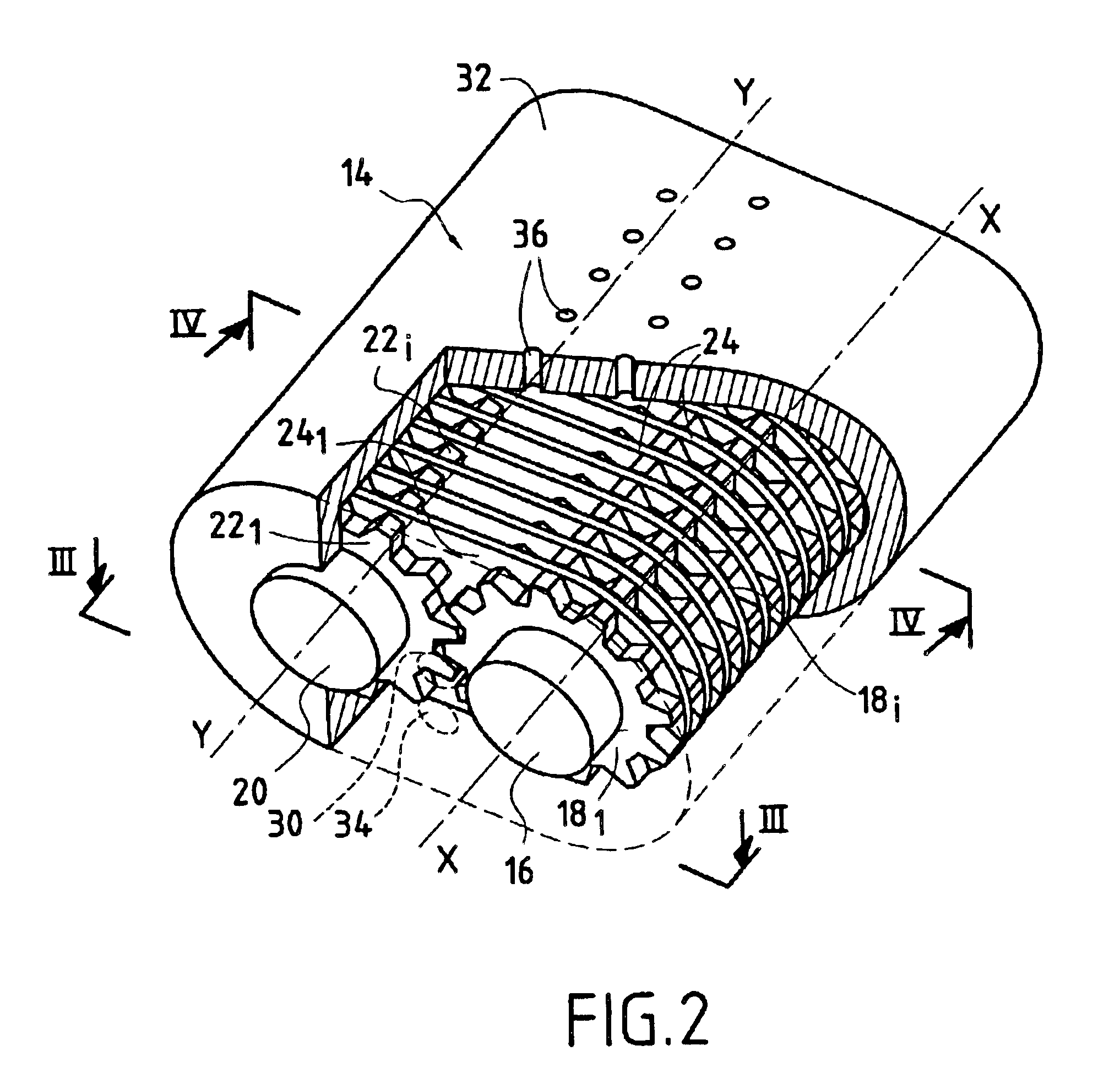
FIGS. 2 to 4 show the single pumping means 14 constituting a particular embodiment of the present ...
PUM
 Abstract
Description
Claims
Application Information