Ultrasound catheter devices and methods

a technology of ultrasound catheter and distal tip, which is applied in the field of medical devices and methods, can solve the problems of not having optimal means for removing particles, not being able to rotate the ultrasound transmission wire, and not having the means to prevent the distal tip from migrating from the device into the patient, etc., to achieve the effect of improving visualization of a location

Active Publication Date: 2007-05-22
FLOWCARDIA
View PDF48 Cites 219 Cited by
  • Summary
  • Abstract
  • Description
  • Claims
  • Application Information

AI Technical Summary

Benefits of technology

[0009]Ultrasound catheter devices and methods provide enhanced disruption of blood vessel obstructions. Generally, ultrasound catheters include an elongate flexible catheter body with one or more lumens, an ultrasound transmission member extending longitudinally through the catheter body lumen and a distal head coupled with the transmission member and positioned adjacent the distal end of the catheter body for disrupting occlusions. Improved features of ultrasound catheters include prevention of independent rotation of the ultrasound transmission member, a safety anchor for the distal head, a one-piece transmission member / distal head and the like.
[0010]In one aspect of the invention, an ultrasound catheter for disrupting occlusions in blood vessels comprises: an elongate flexible catheter body having a proximal end, a distal end and at least one lumen; an ultrasound transmission member extending longitudinally through the lumen of the catheter body and having a proximal end and a distal end; a distal head coupled with the distal end of the ultrasound transmission member and disposed adjacent the distal end of the catheter body; a sonic connector coupled with the proximal end of the ultrasound transmission member for coupling the ultrasound transmission member with an ultrasound transducer device; and a connector housing coupled with the proximal end of the catheter body for housing the sonic connector and a proximal portion of the ultrasound transmission wire and for preventing the ultrasound transmission member from rotating relative to the catheter body.
[0023]In yet another aspect, a method for disrupting an occlusion in a blood vessel involves: positioning an ultrasound catheter in the blood vessel such that a distal end of the catheter is adjacent the occlusion; introducing at least one radiopaque fluid into the blood vessel through at least one aperture in the ultrasound catheter adjacent the distal end to enhance visualization of a location of the distal end; and transmitting ultrasound energy to an ultrasound transmission member of the ultrasound catheter to disrupt the occlusion into multiple occlusion fragments. Optionally, introducing the radiopaque fluid may comprise introducing through at least one irrigation aperture in the ultrasound catheter. Alternatively, introducing the radiopaque fluid may comprise introducing through at least one guidewire aperture in the ultrasound catheter. In yet other embodiments, introducing the radiopaque fluid comprises introducing through a sheath surrounding a portion of the ultrasound catheter and forming the at least one aperture.

Problems solved by technology

In these devices, it is not possible to rotate the ultrasound transmission wire by rotating, for example, a proximal handle or sonic connector assembly, since the transmission wire rotates freely and independently of the catheter body and such a proximal assembly.
Another potential drawback of currently available devices is that they often to not include optimal means for removing particles that are broken up or dislodged by the catheter.
Yet another possible shortcoming is that many ultrasound catheter devices include a distal tip, as mentioned above, but do not have means for preventing the distal tip from migrating from the device into the patient's body if the tip breaks.
Similarly, most ultrasound transmission members include multiple components for transmitting vibrational energy, which causes stresses at the connection points of the multiple components during use and potential breakage of the ultrasound transmission wire or other components.
Also, ultrasound transmission wires are often exposed to increased amounts of stress due to one or more bends in patient vasculature, causing increased wear and tear on the transmission wire.

Method used


Image

  • Ultrasound catheter devices and methods
  • Ultrasound catheter devices and methods
  • Ultrasound catheter devices and methods

Examples


Embodiment Construction

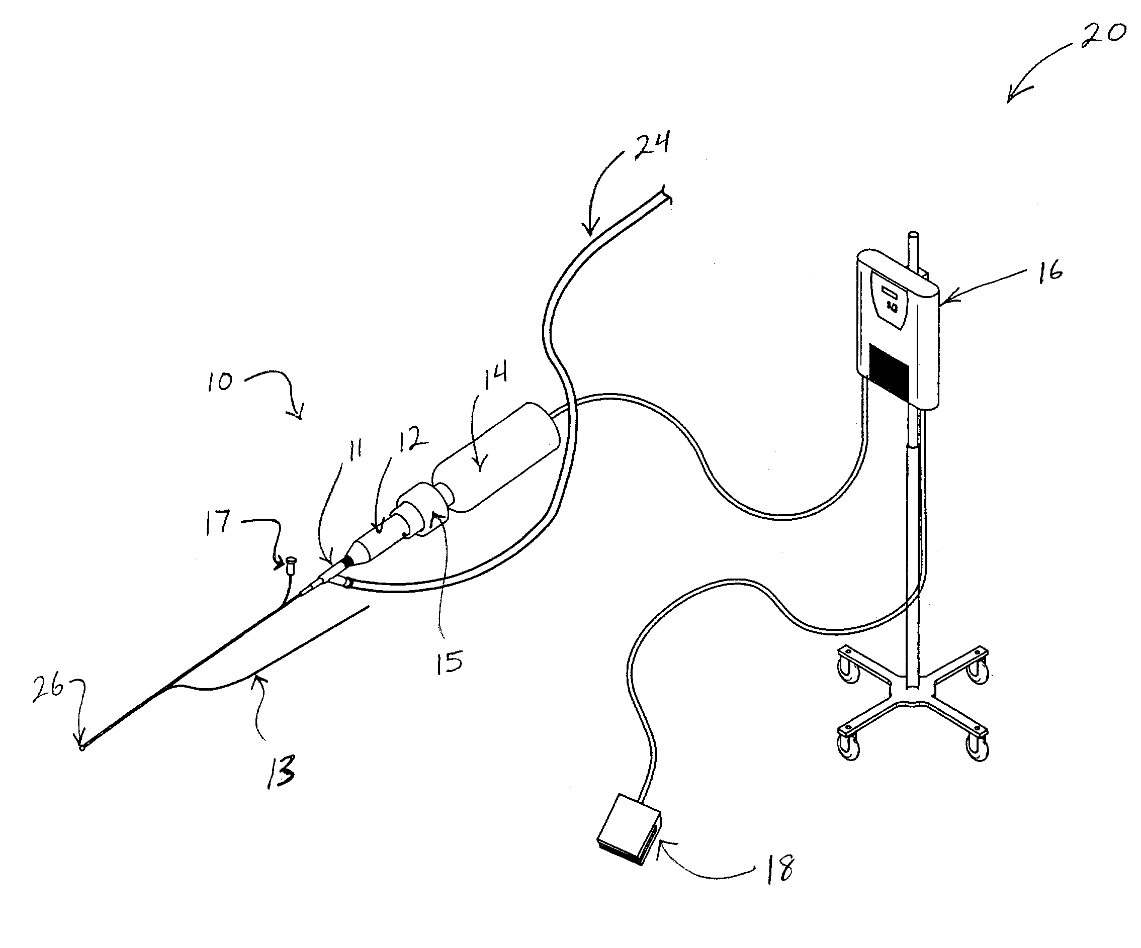
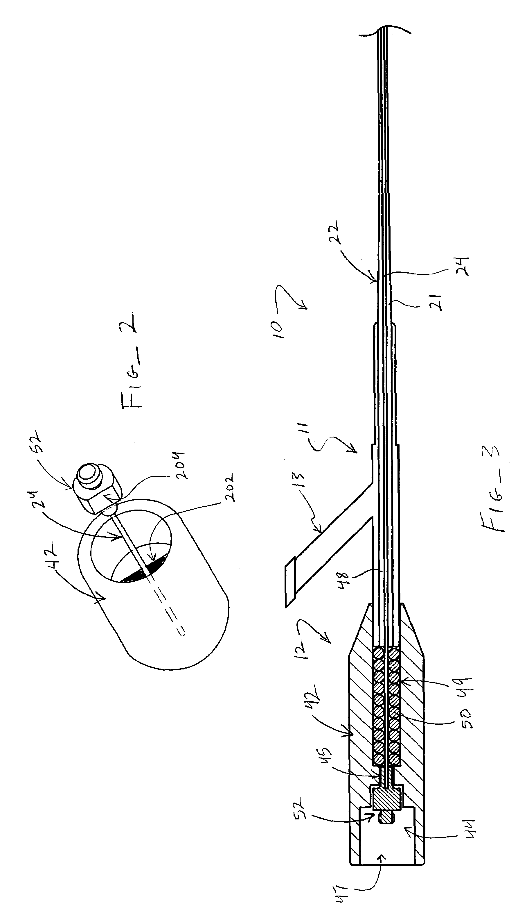
[0036]Ultrasound catheter devices and methods of the present invention may generally be used for treating occlusions in blood vessels. Catheter devices generally include a catheter body, an ultrasound energy transmission member disposed within the catheter body and a distal head coupled with the energy transmission member and disposed at or near the distal end of the catheter body. The ultrasound transmission member transmits ultrasound energy from an ultrasound transducer to the distal head, causing the head to vibrate and, thus, disrupt vascular occlusions. A number of improved features of such ultrasound catheter devices are described more fully below.

[0037]Referring now to FIG. 1, one embodiment of an ultrasound catheter system 20 suitably includes an ultrasound catheter device 10, including a proximal end connector 12 for coupling device 10 with an ultrasound transducer 14, and an ultrasound generator 16 coupled with transducer 14 and a foot-actuated on / off switch 18 to provide...


PUM

PropertyMeasurementUnit
densityaaaaaaaaaa
elongationaaaaaaaaaa

Abstract

Ultrasound catheter devices and methods provide enhanced disruption of blood vessel obstructions. Generally, ultrasound catheters include an elongate flexible catheter body with one or more lumens, an ultrasound transmission member extending longitudinally through the catheter body lumen and a distal head coupled with the transmission member and positioned adjacent the distal end of the catheter body for disrupting occlusions. Improved features of ultrasound catheters include prevention of independent rotation of the ultrasound transmission member, a safety anchor for the distal head, a one-piece transmission member / distal head and the like.

Description

[0001]This application is related to the following pending U.S. patent applications, the full disclosures of which are all hereby incorporated by reference: application Ser. No. 10 / 229,371, filed Aug. 26, 2002, entitled “Ultrasound Catheter for Disrupting Blood Vessel Obstructions,”; application Ser. No. 10 / 345,078, filed Jan. 14, 2003, entitled “Ultrasound Catheter and Methods for Making and Using Same,”; and application Ser. No. 10 / 375,903, now U.S. Pat. No. 6,942,677 filed Feb. 26, 2003, entitled “Ultrasound Catheter Apparatus.”BACKGROUND OF THE INVENTION[0002]The present invention relates generally to medical devices and methods. More specifically, the present invention relates to ultrasound catheter devices and methods for treating occlusive intravascular lesions.[0003]Catheters employing various types of ultrasound transmitting members have been successfully used to ablate or otherwise disrupt obstructions in blood vessels. Specifically, ablation of atherosclerotic plaque or t...

Claims


Application Information

Patent Timeline
Patent Type & Authority Patents(United States)
IPC IPC(8): A61H1/00A61B17/00A61B17/22
CPCA61B17/22012A61B2017/00292A61B2017/22014A61B2017/22015Y10S29/019A61B2017/22065A61B2017/320084A61B2017/320088A61B2017/0046A61B2017/22039A61B2017/00477
Inventor NITA, HENRYSARGE, JEFFNGUYEN, SIMEONSPANO, RICHARD
Owner FLOWCARDIA
Why Eureka
Try Eureka