Ultrasound catheter and methods for making and using same

a technology of ultrasound catheter and ultrasound tube, which is applied in the field of ultrasound catheter devices, can solve the problems of compounding the susceptibility to premature breakage, and reducing the usable life of ultrasound catheters, so as to facilitate positioning and/or advancement, enhance lubricity, and enhance the effect of disruption of blood vessel obstructions

Inactive Publication Date: 2010-01-28
FLOWCARDIA
View PDF99 Cites 20 Cited by
  • Summary
  • Abstract
  • Description
  • Claims
  • Application Information

AI Technical Summary

Benefits of technology

[0007]Ultrasound catheter devices and methods of the present invention provide enhanced disruption of blood vessel obstructions. Generally, ultrasound catheters include an elongate flexible catheter body with at least one lumen, an ultrasound transmission member extending longitudinally through the lumen and, in many embodiments, a guidewire tube extending through the lumen. A distal head for disrupting occlusions is coupled with the distal end of the ultrasound transmission member and is positioned adjacent the distal end of the catheter body. Various embodiments include novel features such as a bend in the catheter body to facilitate positioning and / or advancement of the catheter, over-the-wire configurations, improved configurations of a distal head of the catheter, catheters that allow for various modes of operation, catheters with enhanced lubricity and the like. Methods for making ultrasound catheters may include methods for making a bend in the catheter, methods for sterilizing a catheter using electron-beam radiation and / or the like.

Problems solved by technology

First, it is inaccurate and does not always result in a bend at a desired location along the catheter or in a bend having a desired angle.
Second, because the user bends the catheter when the catheter is already assembled, with the transmission member already in place, a strain is placed on the transmission member by the bending process.
Even slight stresses placed on the transmission member by such a bending procedure may cause the transmission member to break prematurely, leading to a reduced usable life for the ultrasound catheter.
This susceptibility for premature breakage is compounded by the fact that currently available ultrasonic transmission wires typically break toward their distal ends, where the cross-sectional areas of the wires become smaller.

Method used


Image

  • Ultrasound catheter and methods for making and using same
  • Ultrasound catheter and methods for making and using same
  • Ultrasound catheter and methods for making and using same

Examples


Embodiment Construction

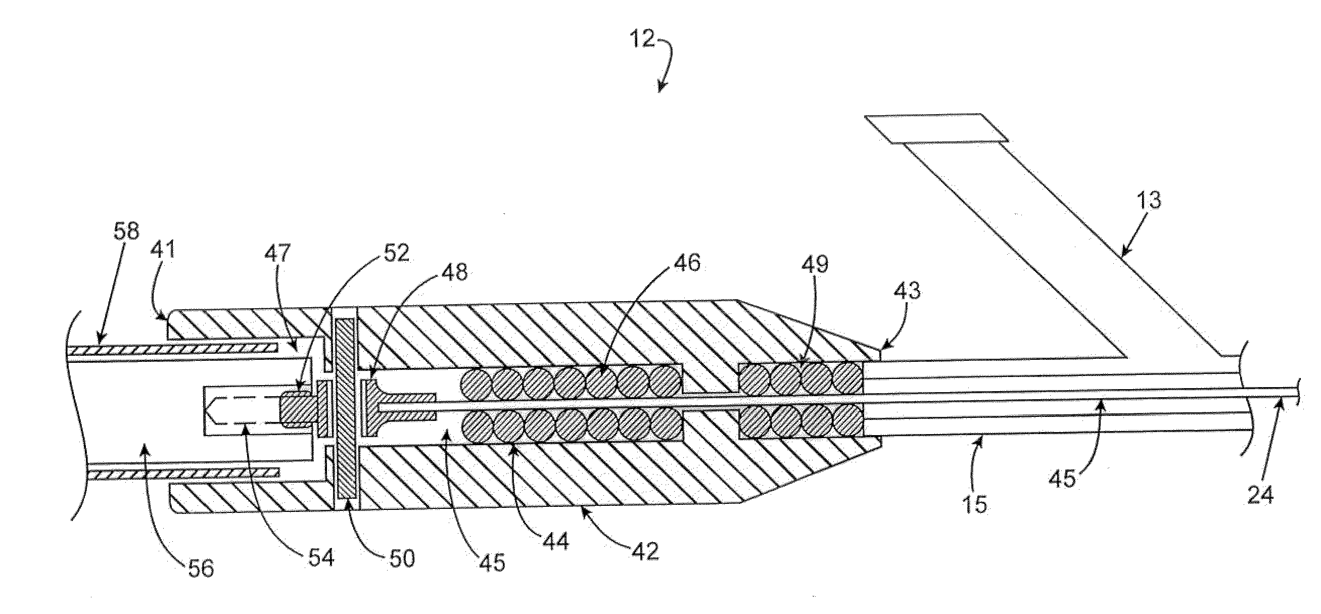
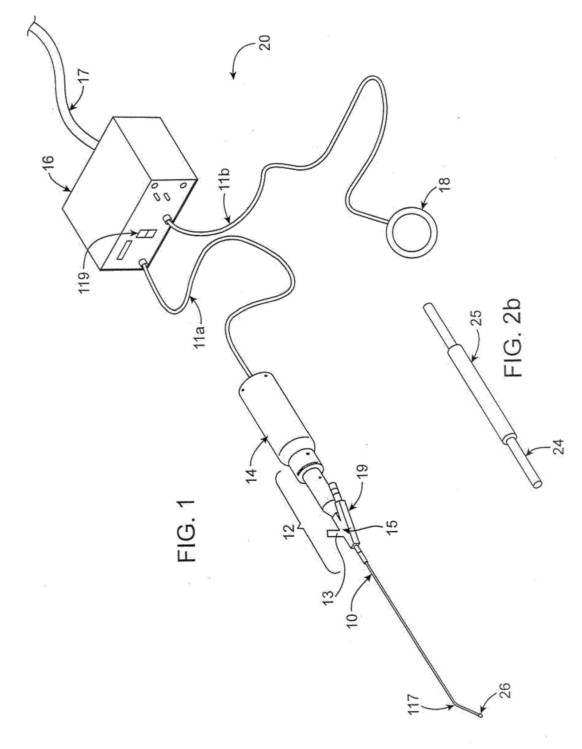
[0043]Ultrasound catheter devices and methods of the present invention may generally be used for treating occlusions in blood vessels. Catheter devices generally include a catheter body, an ultrasound energy transmission member disposed within the catheter body and a distal head coupled with the energy transmission member and disposed at or near the distal end of the catheter body. The ultrasound transmission member transmits ultrasound energy from an ultrasound transducer to the distal head, causing the head to vibrate and, thus, disrupt vascular occlusions.

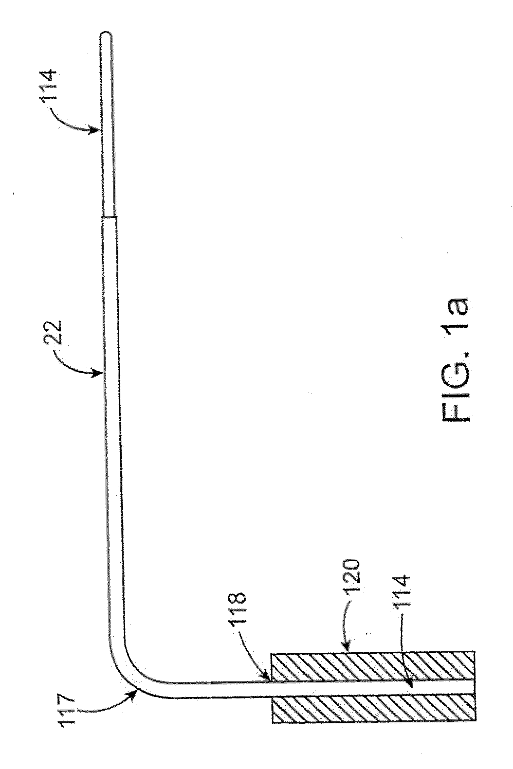
[0044]Some embodiments of an ultrasound catheter include at least one bend in the catheter body for enhancing positioning and / or advancement of the catheter in a blood vessel. A bend may facilitate, for example, placement or repositioning of the catheter in a branching vessel that branches off of a larger vessel. The bend in the catheter body is typically formed by heating the body while it is on a mandrel, but other suitable me...


PUM


Abstract

Ultrasound catheter devices and methods provide enhanced disruption of blood vessel obstructions. Generally, ultrasound catheters include an elongate flexible catheter body with one or more lumens, an ultrasound transmission member extending longitudinally through the catheter body lumen and, in some embodiments, a guidewire tube extending through the lumen. A distal head for disrupting occlusions is coupled with the distal end of the ultrasound transmission member and is positioned adjacent the distal end of the catheter body. Some embodiments include improved features such as a bend in the catheter body for enhancing positioning and / or advancement of the catheter.

Description

CROSS-REFERENCES TO RELATED APPLICATIONS[0001]This application is a continuation of U.S. patent application Ser. No. 10 / 345,078, entitled Ultrasound Catheter and Methods for Making and Using Same, filed on Jan. 14, 2003 which is related to pending U.S. patent application Ser. No. 10 / 229,371, entitled “Ultrasound Catheter for Disrupting Blood Vessel Obstructions,” the full disclosures of which are hereby incorporated by reference.BACKGROUND OF THE INVENTION[0002]The present invention relates generally to medical devices and methods. More specifically, the present invention relates to ultrasound catheter devices, methods for making the devices, and methods for using the devices to disrupt blood vessel occlusions.[0003]Catheters employing various types of ultrasound transmitting members have been successfully used to ablate or otherwise disrupt obstructions in blood vessels. Specifically, ablation of atherosclerotic plaque or thromboembolic obstructions from peripheral blood vessels su...

Claims


Application Information

Patent Timeline
Patent Type & Authority Applications(United States)
IPC IPC(8): A61N7/00A61B17/00A61B17/22A61M25/095
CPCA61B17/22012A61B2017/320084A61B2017/00154A61B2017/00292A61B2017/003A61B2017/00331A61B2017/00526A61B2017/22011A61B2017/22014A61B2017/22015A61M25/0009A61M25/001A61M25/0041A61B17/320068A61B2017/320072A61B2017/00141
Inventor NITA, HENRYSARGE, JEFFNGUYEN, SIMON
Owner FLOWCARDIA
Why Eureka
Try Eureka