
Ultrasound catheter for disrupting blood vessel obstructions

a technology of ultrasound catheter and blood vessel, applied in the field of medical devices and methods, can solve the problems of affecting the treatment effect of patients, affecting the treatment effect, and the ultrasound transmission member, etc., to achieve the effect of enhancing the disruption of blood vessel obstruction

Inactive Publication Date: 2007-01-25
FLOWCARDIA
View PDF16 Cites 22 Cited by
  • Summary
  • Abstract
  • Description
  • Claims
  • Application Information

AI Technical Summary

Benefits of technology

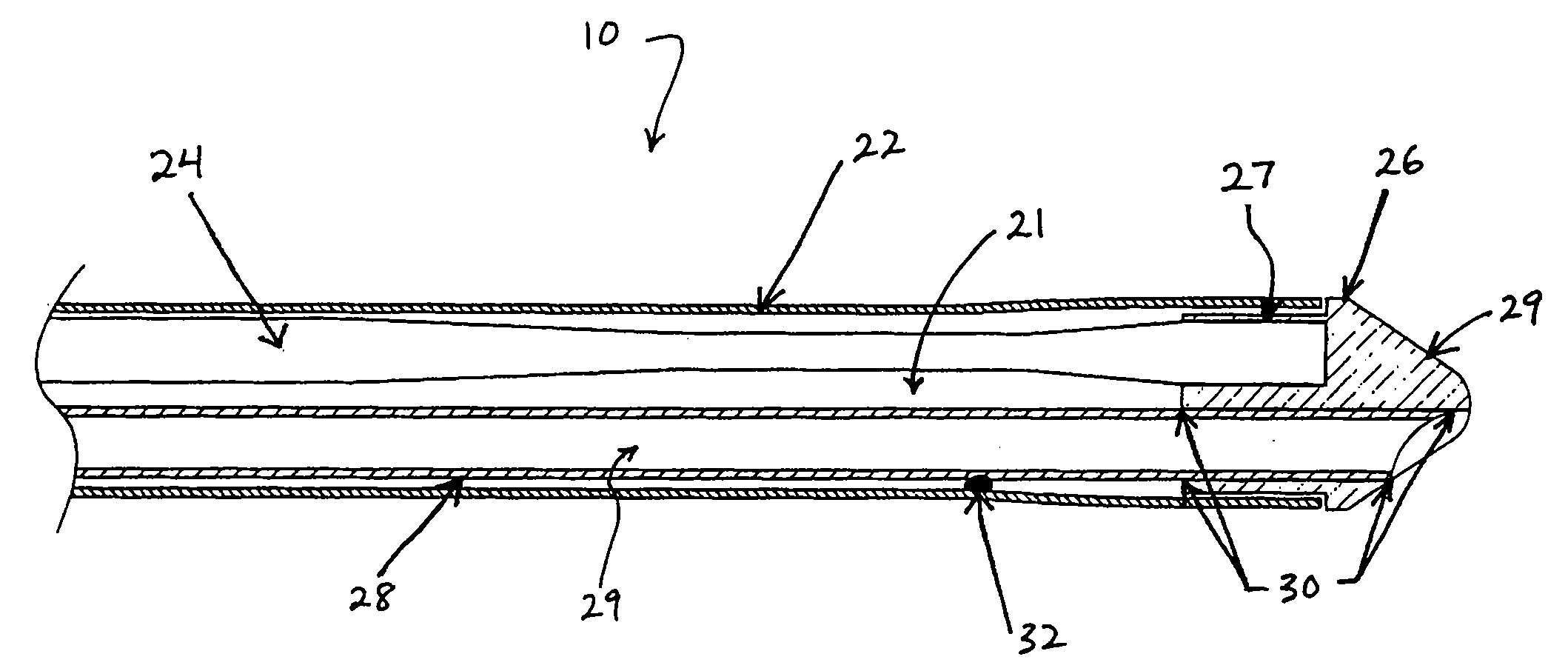
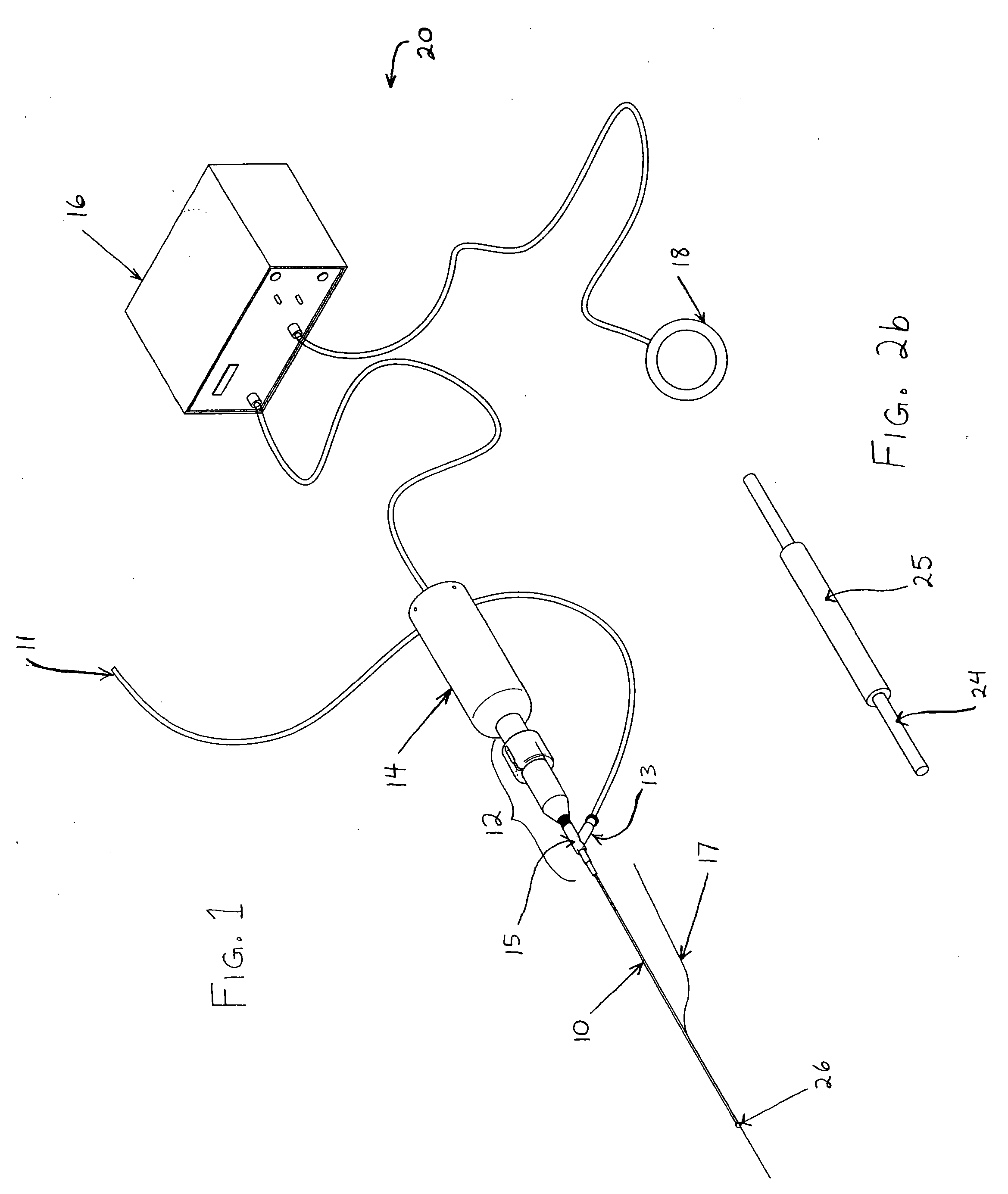
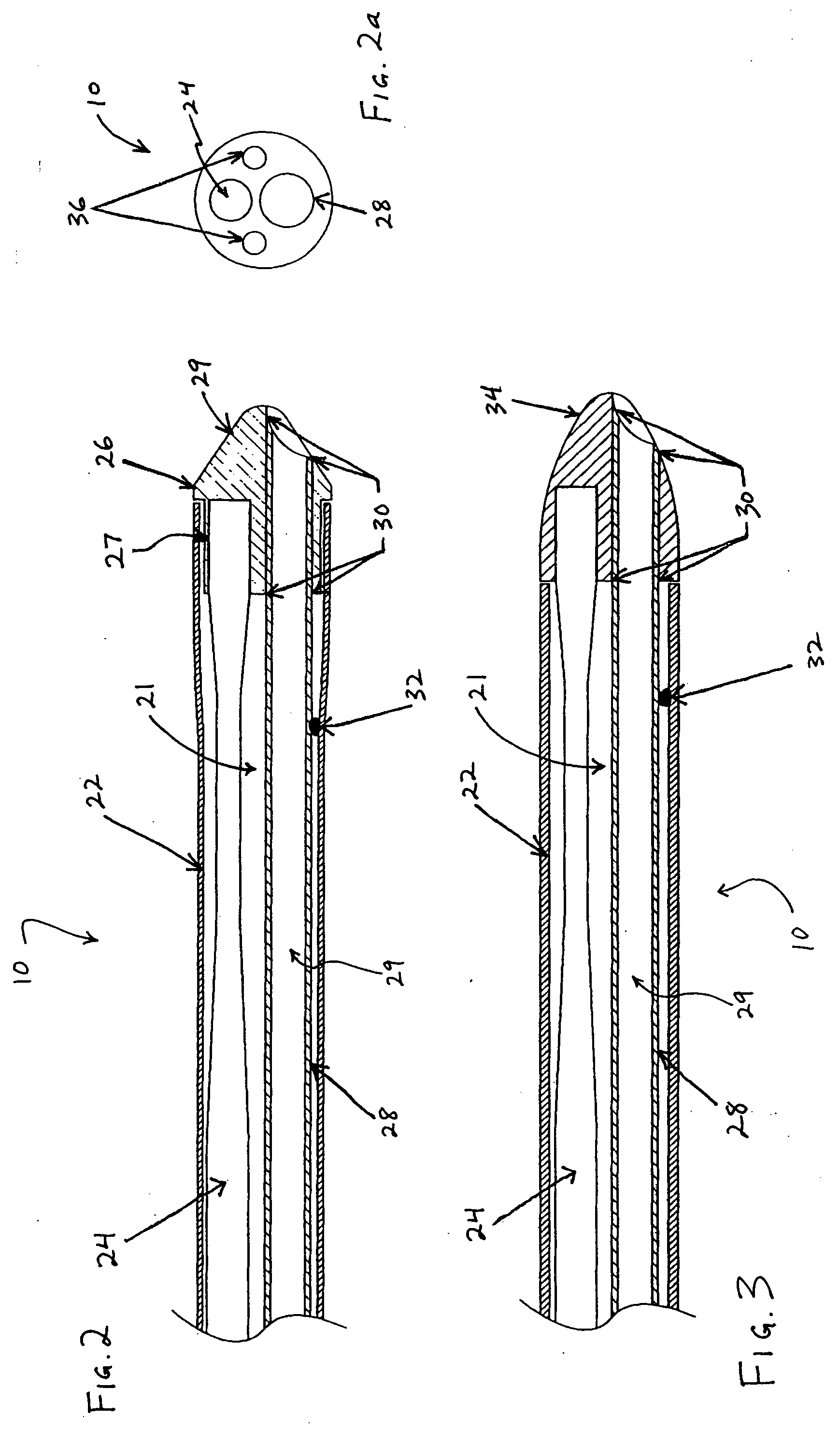
[0011] Ultrasound catheter devices and methods of the present invention provide enhanced disruption of blood vessel obstructions. Generally, an ultrasound catheter includes an elongate flexible catheter body with one or more lumens. An ultrasound transmission member or wire extends longitudinally through the catheter body lumen and, in many embodiments, a guide wire tube also extends through the same lumen. A distal head is fixed to or otherwise mechanically coupled with the distal end of the ultrasound transmission member or wire and is positioned adjacent the distal end of the catheter body. Although the distal end of the catheter body often overlaps the distal head, the distal head is not directly affixed to the distal end of the catheter body. Thus, the distal tip may move freely (or “float”), relative to the distal end of the catheter body when ultrasonic energy is applied through the ultrasound transmission member.
[0012] A free-floating distal head enhances the ability of an ultrasonic catheter to disrupt vascular occlusions by using ultrasonic energy more efficiently. Basically, less energy is required to vibrate a floating distal head in a longitudinal direction for disrupting an occlusion. By using less ultrasonic energy, fewer unwanted transverse vibrations are created, thus reducing stress and fatigue of the ultrasound transmission member and increasing catheter longevity. The increased efficiency of such a free-floating head ultrasound catheter may be used to effectively disrupt calcific intravascular occlusions. In many embodiments, the distal end of the catheter body will overlap at least a portion of the distal head, to impart stability to the free-floating head.
[0015] Generally, the distal head of the catheter may be fabricated from any suitable material, including but not limited to a metal or a polymer. In some embodiments, the distal head includes one or more radiopaque markers to improve its visibility via radiographic techniques.
[0017] Optionally, ultrasound catheters may also include a distal sleeve, coupled with the catheter body within the lumen of the catheter body. Such a sleeve will typically comprise a hollow, cylindrical member that surrounds a portion of the ultrasound transmission member. The sleeve enhances stability of the catheter when the catheter is twisted or torqued by a physician during use. For additional safety, some embodiments include an anchor member disposed within the lumen of the catheter body. The anchor member will generally have a distal end coupled with the distal head and a proximal end coupled with the catheter body. In some embodiments, the anchor will comprise a wire.
[0022] In many embodiments, the ultrasound transmission member includes one or more tapered regions near its distal end. For example, in some embodiments one or more tapered regions divide the ultrasound transmission member into a proximal portion and a distal portion. In many embodiments, the proximal portion has a larger diameter than the distal portion. Also in many embodiments, the distal portion of the ultrasound transmission member has a greater cross-sectional diameter than the tapered region, to enhance coupling of the distal portion of the member to the distal head. The tapered regions of transmission member generally provide it with enhanced flexibility.

Problems solved by technology

One difficulty related to transmission of ultrasound energy through long catheters is premature wear and tear and breakage of the catheter body, the ultrasound transmission member, or both.
A stronger, more durable transmission wire allows for greater transmission of energy and is more durable than a thinner wire, but it may not be flexible or thin enough to be advanced through the vasculature to a desired treatment area.
A thinner wire is less durable and more susceptible to breakage.
Wire breakage is generally caused by stress concentration due to transverse vibrations and fatigue.
The longitudinal vibrations typically create the beneficial effects of disrupting an occlusion, while the transverse vibrations are predominantly unwanted artifact that stresses and fatigues the transmission member.
Such a solution is significantly limited, however, by the structural requirements of an ultrasound catheter.
Placing one or more vibration absorbers at or near the distal end typically increases the diameter of the catheter, interferes with the continuous irrigation system, or both.
With such an affixed distal head, however, more ultrasound energy is required to produce a desired amount of longitudinal vibration to disrupt or ablate a vascular occlusion.
Ironically, increasing the ultrasound energy applied to the transmission wire may actually cause increased stress on the wire and, consequently, premature wire fatigue and breakage.
Another challenge in developing ultrasound catheters is to provide sufficient mechanical energy at the distal head to break through calcified plaque.
At the present time, neither ultrasound catheters nor any other comparable devices have solved the problem of calcific plaque occlusions in blood vessels.

Method used


Image

  • Ultrasound catheter for disrupting blood vessel obstructions
  • Ultrasound catheter for disrupting blood vessel obstructions
  • Ultrasound catheter for disrupting blood vessel obstructions

Examples


Embodiment Construction

[0036] Ultrasound catheter devices and methods of the present invention generally provide for ablation and disruption of intravascular occlusions, including calcified occlusions. An ultrasound energy transmission member, such as a wire, typically transmits energy from an ultrasound transducer to a distal head of the catheter. The transmitted energy causes the distal head to vibrate, and such vibrational energy may be used to ablate vascular occlusions. Typically, the distal head of the ultrasound catheter is not directly affixed to the catheter body, which allows the distal head to move freely (or “float”), relative to the distal end of the catheter body. This freedom of movement generally provides increased energy transmission efficiencies, with reduced stress on the ultrasound transmission wire and, therefore, less wear and tear and premature breakage of the wire. Additionally, an unaffixed distal head may provide greater ablative capabilities, so that calcified occlusions may be ...


PUM


Abstract

Ultrasound catheter devices and methods provide enhanced disruption of blood vessel obstructions. Generally, an ultrasound catheter includes an elongate flexible catheter body with one or more lumens. An ultrasound transmission member or wire extends longitudinally through the catheter body lumen and, in many embodiments, a guide wire tube also extends through the same lumen. A distal head is fixed to or otherwise mechanically coupled with the distal end of the ultrasound transmission member or wire and is positioned adjacent the distal end of the catheter body. Although the distal end of the catheter body overlaps the distal head, the distal head is not directly affixed to the distal end of the catheter body. Thus, the distal tip may move freely, relative to the distal end of the catheter body when ultrasonic energy is applied through the ultrasound transmission member. Such a freely floating distal head enhances the efficiency of an ultrasound catheter, enabling the catheter to ablate calcific occlusions and increasing the useful life of the ultrasound transmission member and catheter.

Description

BACKGROUND OF THE INVENTION [0001] The present invention relates generally to medical devices and methods. More specifically, the present invention relates to ultrasound catheter devices and methods for treating occlusive intravascular lesions. [0002] Catheters employing various types of ultrasound transmitting members have been successfully used to ablate or otherwise disrupt obstructions in blood vessels. Specifically, ablation of atherosclerotic plaque or thromboembolic obstructions from peripheral blood vessels such as the femoral arteries has been particularly successful. To disrupt occlusions of small blood vessels, such as the coronary arteries, ultrasound catheters must typically be sufficiently small and flexible to permit their advancement through the tortuous vasculature of the aortic arch, coronary tree, or other similarly narrow vasculature. Thus, safely and effectively disrupting or ablating obstructions from coronary arteries with ultrasound energy devices depends lar...

Claims


Application Information

Patent Timeline
Patent Type & Authority Applications(United States)
IPC IPC(8): A61H1/00A61B18/00A61B17/22A61B17/32A61M25/00
CPCA61B17/22012A61B2017/00477A61B2017/22015A61B17/22A61B2017/320072A61B2017/320084A61B2017/22018A61B2017/320073A61B2017/22038A61M37/0092
Inventor NITA, HENRYSARGE, JEFFTRAN, MARTINOSNGUYEN, SIMON
Owner FLOWCARDIA
Learn More