Buffy coat separator float system and method

a float system and buffy coat technology, applied in separation processes, laboratory glassware, centrifuges, etc., can solve the problems of difficult measurement and low number of cells expected to be typically present in the buffy coat, and achieve the effect of reducing centrifugation speed, reducing possible tube failure, and improving buffy coat separation

Inactive Publication Date: 2007-05-22
BATTELLE MEMORIAL INST
View PDF20 Cites 76 Cited by
  • Summary
  • Abstract
  • Description
  • Claims
  • Application Information

AI Technical Summary

Benefits of technology

[0015]One advantage of the present invention is found in a blood separating apparatus that can separate the entire buffy coat of a relatively large blood sample from the rest of the blood volume.
[0016]Another advantage of the invention resides in the fact that the buffy coat layers can be made available for visualization or imaging in one simple operation, i.e., centrifugation.
[0017]Still another advantage of the invention resides in enhanced buffy coat separation, retention, and, if desired, removal from the sample tube for further processing.
[0018]Another advantage of the invention resides in that reduced centrifugation speeds can be used to spin down the blood sample, thereby reducing possible tube failures.
[0019]Still another advantage is found in that the tube can be supported for improved imaging of the sample, and a more repeatable depth for imaging may be provided.
[0020]Still further advantages of the present invention reside in its relatively simple construction, ease of manufacture, and low cost.

Problems solved by technology

However, the number of cells expected to be typically present in the buffy coat is very low relative to the volume of blood, for example, in the range of about 1–100 cells per millimeter of blood, thus making the measurement difficult, particularly with the very small sample sizes employed with the conventional QBC capillary tubes and floats.

Method used


Image

  • Buffy coat separator float system and method
  • Buffy coat separator float system and method
  • Buffy coat separator float system and method

Examples


Embodiment Construction

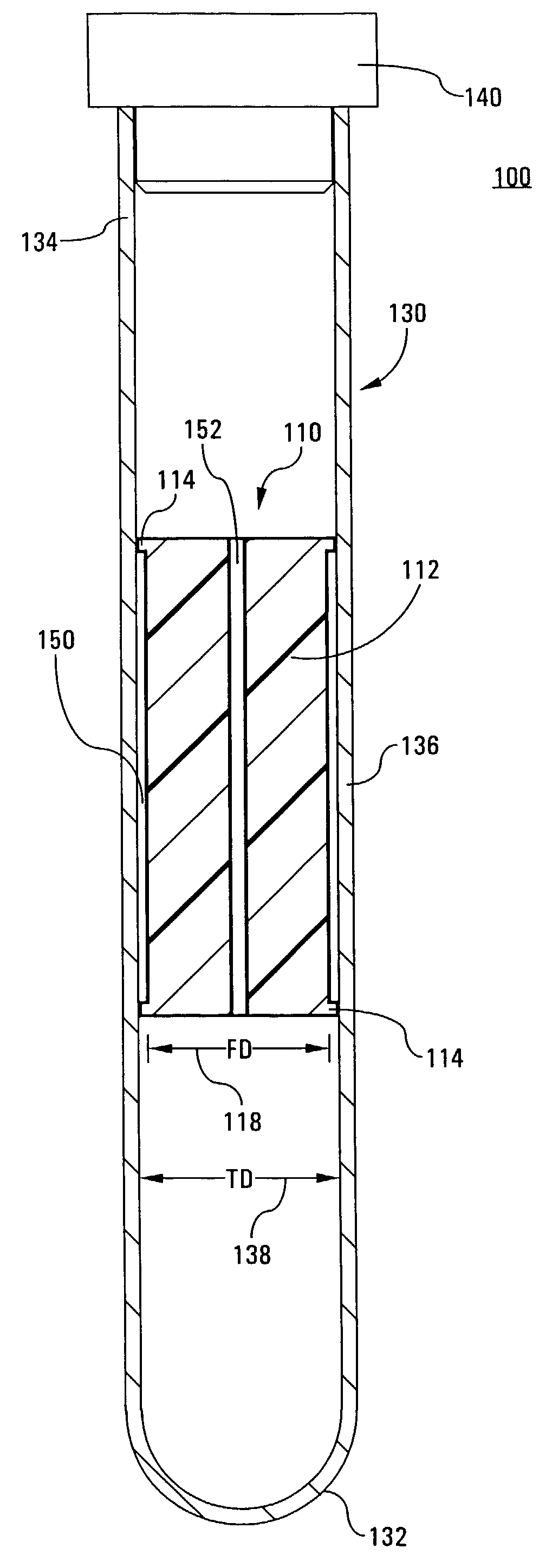
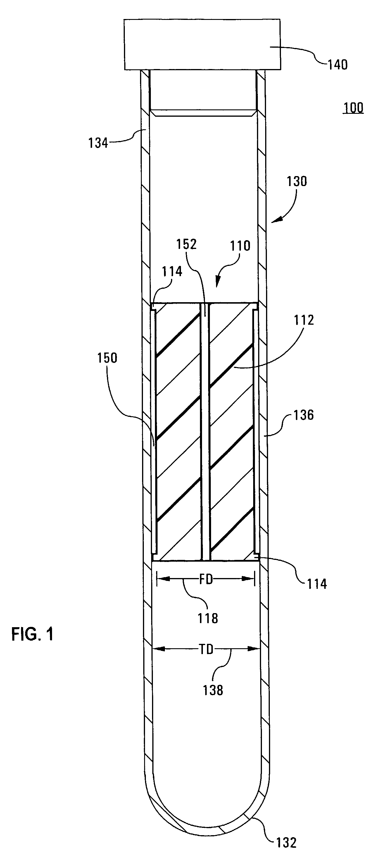
[0030]Turning now to the drawings, wherein the showings are for purposes of illustrating the preferred embodiments of the invention only and not for limiting the same, FIG. 1 shows a blood separation tube and float assembly 100, including a sample tube 130 having a separator float or bobber 110 of the invention therein.

[0031]The sample tube 130 is generally cylindrical in the depicted embodiment, although tubes having polygonal and other geometrical cross-sectional shapes are also contemplated. The sample tube 130 includes a first, closed end 132 and a second open end 134 receiving a stopper or cap 140. Other closure means are also contemplated, such as parafilm or the like. In alternative embodiments, not shown, the sample tube may be open at each end, with each end receiving an appropriate closure device.

[0032]Although the tube is depicted as generally cylindrical, the tube 130 may be minimally tapered, slightly enlarging toward the open end 134, particularly when manufactured by ...


PUM

PropertyMeasurementUnit
densityaaaaaaaaaa
densityaaaaaaaaaa
inner diameteraaaaaaaaaa

Abstract

A tube and float system for use in separation and axial expansion of the buffy coat includes a transparent or semi-transparent, flexible sample tube and a rigid separator float having a specific gravity intermediate that of red blood cells and plasma. The float includes a main body portion of reduced diameter to provide a clearance gap between the inner wall of the sample tube and the float. One or more protrusions on the main body portion serve to support the flexible tube. During centrifugation, the centrifugal force causes the diameter of the flexible tube to expand and permit density-based axial movement of the float in the tube. The float further includes a pressure relief system to alleviate pressure build up in the trapped red blood cell blood fraction below the float, thereby preventing red blood cells from being forced into the annular gap containing the buffy coat layers.

Description

INCORPORATION BY REFERENCE[0001]U.S. application Ser. No. 10 / 263,975, filed Oct. 3, 2002, now U.S. Pat. No. 7,074,577, issued on Jul. 11, 2006, is incorporated herein by reference in its entirety.FIELD OF THE INVENTION[0002]The present invention relates generally to density-based fluid separation and, in particular, to an improved sample tube and float design for the separation and axial expansion of constituent fluid components layered by centrifugation, and a method employing the same. The present invention finds particular application in blood separation and axial expansion of the buffy coat layers, and will be described with particular reference thereto. However, it will be recognized that the present invention is also amenable to other like applications.BACKGROUND OF THE INVENTION[0003]Quantitative Buffy Coat (QBC) analysis is routinely performed in clinical laboratories for the evaluation of whole blood. QBC analysis techniques generally employ centrifugation of capillary tube...

Claims


Application Information

Patent Timeline
Patent Type & Authority Patents(United States)
IPC IPC(8): G01N1/18G01N33/48B01L3/14G01N33/50
CPCB01L3/50215G01N33/491G01N33/5094Y10T436/111666Y10T436/25Y10T436/25375
Inventor HAUBERT, THOMASCONTINI, VINCEGRIMES, STEVEJONES, RANDYWARDLAW, STEPHAN C.
Owner BATTELLE MEMORIAL INST
Why Eureka
Try Eureka