
Power generation system having an external process module

a technology of power generation system and process module, which is applied in the direction of emergency power supply arrangement, machines/engines, transportation and packaging, etc., can solve the problems of insufficient support of weight, time-consuming and expensive process, and other problems,

Inactive Publication Date: 2007-05-22
CATERPILLAR INC
View PDF28 Cites 53 Cited by
  • Summary
  • Abstract
  • Description
  • Claims
  • Application Information

AI Technical Summary

Benefits of technology

[0008]Another embodiment of a power generation system has a power module and an external process module. The power module has a housing having a height dimension. The external process module has a frame having a height dimension. The height dimension of the frame of the external process module is less than the height dimension of the housing of the power module.

Problems solved by technology

However, the process of adding the aftertreatment systems to the power generation systems has revealed several problems.
This process is both time consuming and expensive.
When an aftertreatment system is to be added to a portable power generation system, other difficulties arise.
The top sides of the housings of most portable power generation systems are not strong enough to support the weight of an aftertreatment system.
Adding these supporting members to the housing increases the time and expense required to install the aftertreatment system.
Transportation problems are also inherent in the current method of adding aftertreatment systems to power generation systems.
Individual aftertreatment elements are not easily transported via typical shipping methods.
Therefore, these modified housings are often too large to be shipped via conventional means.
Stacking such units on top of each other could result in wind loads on the system of sufficient strength to cause damage to the system.
In addition, the driven units in the '669 patent do not provide support for internal engine processes but merely use the power created by the driving units.

Method used


Image

  • Power generation system having an external process module
  • Power generation system having an external process module
  • Power generation system having an external process module

Examples


Embodiment Construction

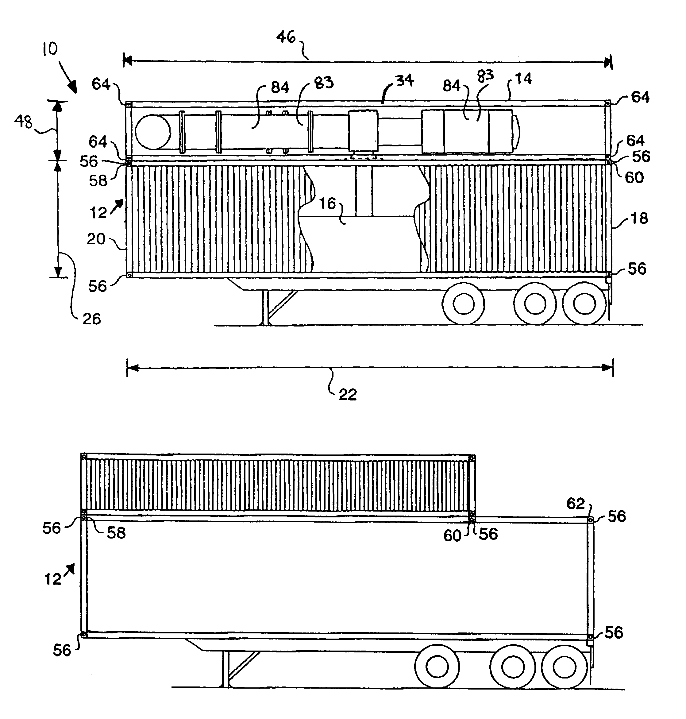
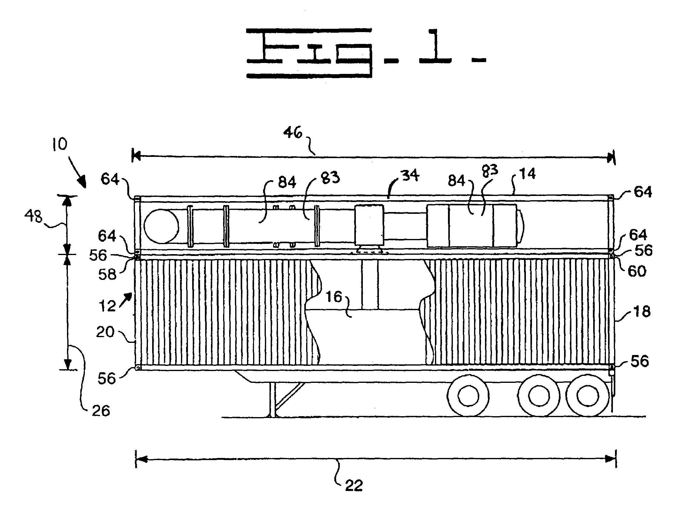
[0016]Referring to FIG. 1, a power generation system 10 is shown. The power generation system 10 includes a power module 12 and an external process module 14 connected to the power module 12. The power module 12 typically includes a power source 16. The power source 16 may be a spark-ignition engine, a compression-ignition engine, a homogenous charge compression ignition engine, a turbine, a fuel cell, or any other power-generating apparatus. As shown in FIG. 1, the power module 12 may be a portable power generation system. However, as used herein “power module” may also include other power generation systems, including custom-built power generation systems, fixed location power generation systems, and portable power generation systems that have been removed from trailers.

[0017]The power module 12 in FIG. 1 includes a housing 18 consisting of an ISO container 20. As used herein, “ISO container” shall mean a container meeting the specifications set forth by the International Standard...


PUM


Abstract

A power generation system includes a power module and an external process module. The external process module may include at least one engine support element. The power module has at least one connection zone, and the external process module has at least one connection zone that is configured to align with the at least one connection zone of the power module. The aligned connection zones of the power module and the external process module permit relatively quick and inexpensive attachment of the external process module to the power module. The at least one engine support element may be an aftertreatment element.

Description

TECHNICAL FIELD[0001]This invention relates generally to power generation systems, and more particularly to an external process module for use with a power generation system.BACKGROUND[0002]In recent years regulatory agencies around the world have instituted changes in the regulations governing the emission levels of power generation systems. The changing of these regulations has resulted in many manufacturers of power generation systems producing aftertreatment systems to be added to their power generation systems. These aftertreatment systems reduce the levels of regulated emissions produced by the power generation systems. However, the process of adding the aftertreatment systems to the power generation systems has revealed several problems.[0003]The typical process of attaching aftertreatment systems to power generation systems involves attaching individual elements of the aftertreatment system to the housing of the power generation system. However, a typical aftertreatment syst...

Claims


Application Information

Patent Timeline
Patent Type & Authority Patents(United States)
IPC IPC(8): F02B63/04F02C6/00F02C6/18F01K15/00H02K7/18F02B1/12H02J7/34H02J9/08
CPCF02B63/04H02J7/34H02J9/08F02B1/12F02B63/044
Inventor ALGER, MATTHEW J.LIANG, CHO Y.WOODS, EDWARD J.
Owner CATERPILLAR INC
Features
  • Generate Ideas
  • Intellectual Property
  • Life Sciences
  • Materials
  • Tech Scout
  • Unparalleled Data Quality
  • Higher Quality Content
  • 60% Fewer Hallucinations
Learn More