Simplified power monitoring system for electrical panels

a power monitoring system and simple technology, applied in the direction of electric devices, instruments, transportation and packaging, etc., can solve the problems of burdensome interconnection of a significant number of power meters, in particular voltage connections to wires, and the trip of the circuit breaker,

Inactive Publication Date: 2007-05-22
VERIS INDS
View PDF15 Cites 33 Cited by
  • Summary
  • Abstract
  • Description
  • Claims
  • Application Information

AI Technical Summary

Problems solved by technology

In this manner, if a load shorts and thereafter draws excessive current then the circuit breaker will trip.
Unfortunately, it is burdensome to interconnect a significant number of power meters and in particular the voltage connections to the wires, especially if an interconnection to the wires are not readily available.
In addition, it is burdensome to interconnect the output of the p

Method used


Image

  • Simplified power monitoring system for electrical panels
  • Simplified power monitoring system for electrical panels
  • Simplified power monitoring system for electrical panels

Examples


Embodiment Construction

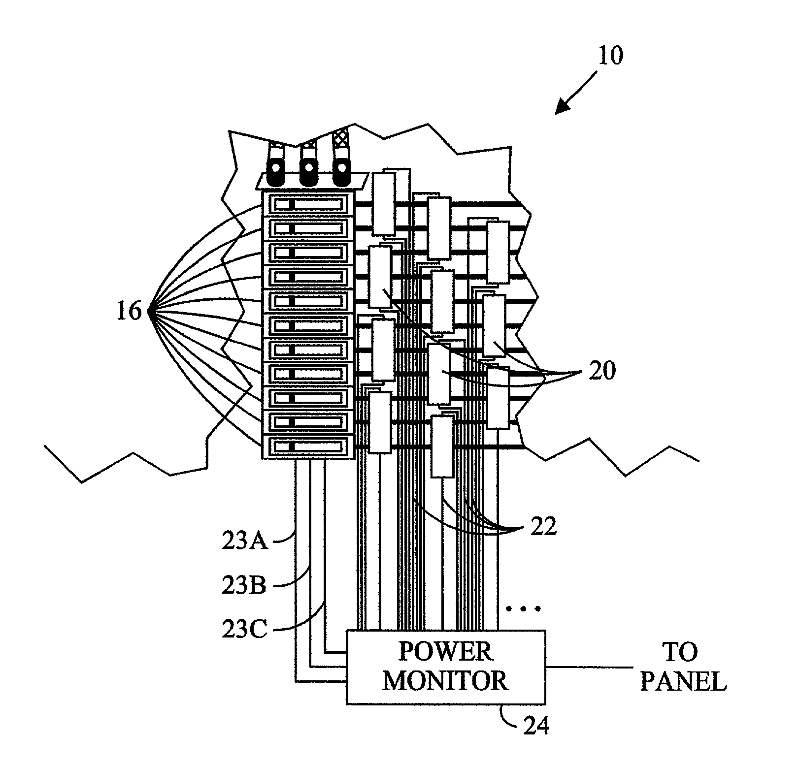
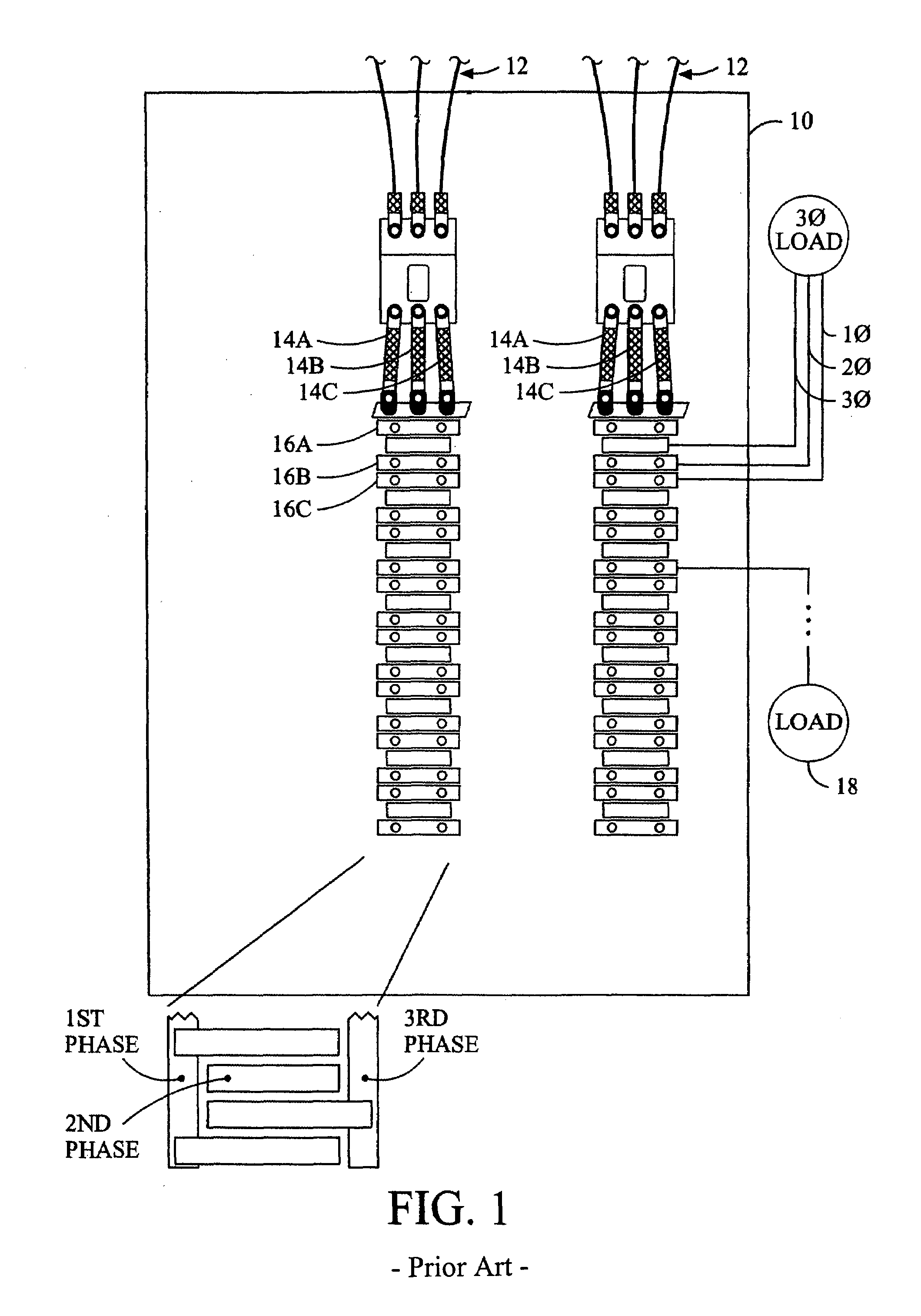
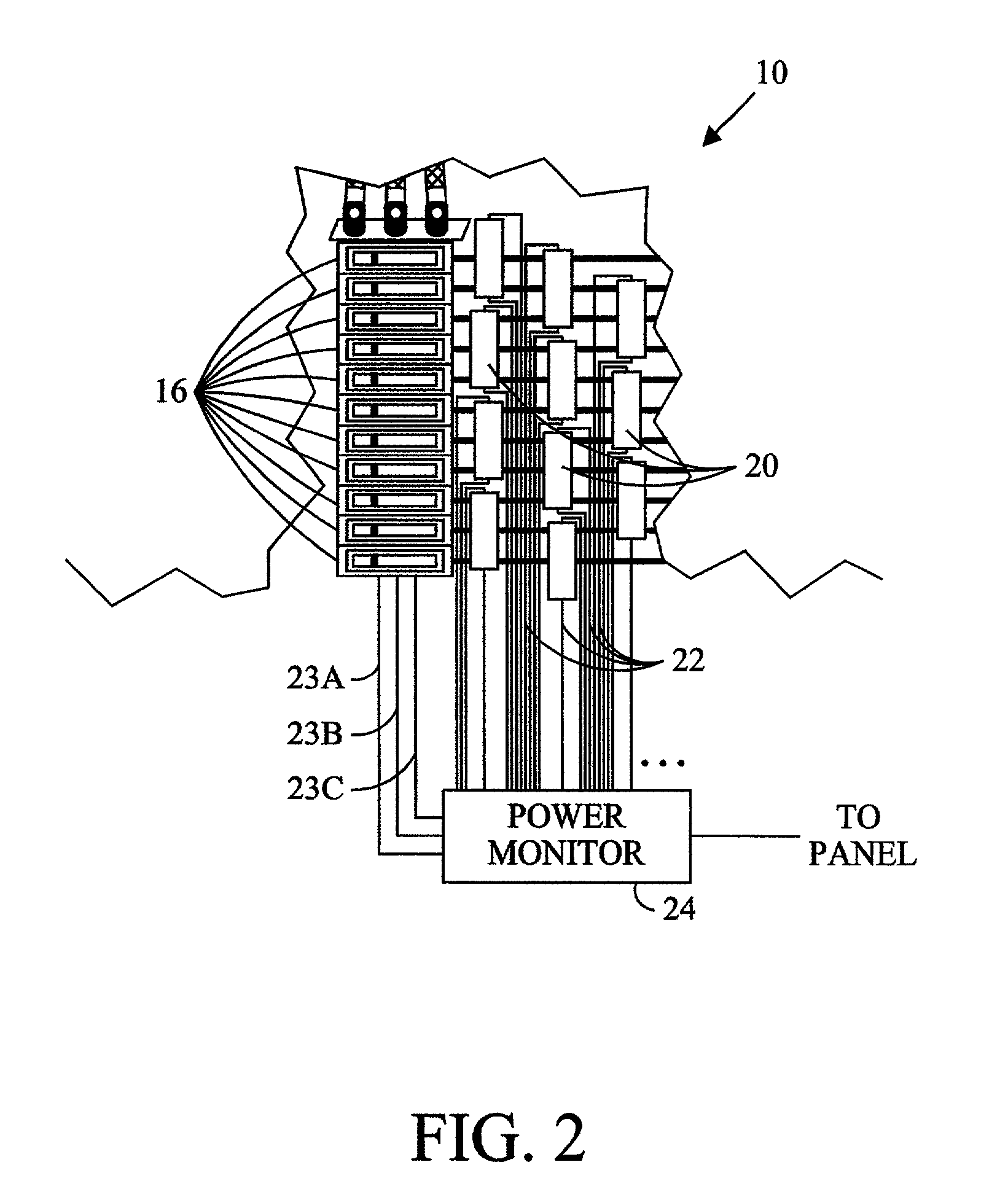
[0017]The present inventors reflected on the aforementioned limitations inherent to using multiple independent power meters for a set of loads and came to the realization that a power panel 10 provides a centralized location where the currents in the wires to several different loads may be sensed and the voltage in the bus bars that correspond with the currents may be sensed, with both being readily available. Moreover, unlike traditionally accepted power meters including multiple current sensors and multiple voltage connections for each load to be measured, the present inventors came to the realization that the power provided from the bus bars to multiple different loads has the same voltage potential and phase relationship with respect to each of the different loads. In other words the power factor, which is a phase relationship between the voltage and current provided to a load, may be determined based on the current to the particular load and the voltage in the respective bus ba...


PUM


Abstract

A power monitoring system for electrical panels providing multi-phase power, with multiple current sensors. The disclosed power monitoring system preferably determines the instantaneous power provided to each of multiple loads by sensing the potential and phase of each conductor that supplies power to one or more of the respective loads.

Description

[0001]This application claims the benefit of U.S. Patent Application Ser. No. 60 / 335,230, filed on Nov. 30, 2001.BACKGROUND OF THE INVENTION[0002]The present invention relates to a power monitoring system.[0003]Referring to FIG. 1, many electrical power distribution systems include a panel enclosure 10 into which is provided electrical power using one or more sets of wires 12. The electrical power may have any voltage, any current, and any number of phases (e.g., single phase, two phases, or three phases). Each phase of the electrical power to the power panel is normally provided to a separate bus bar 14a, 14b, and 14c, which are normally elongate conductors within the power panel 10. A plurality of circuit breakers 16a, 16b, and 16c, etc., which trip or otherwise selectively disconnect electrical power, are electrically interconnected between one or more of the bus bars 14a, 14b, and 14c, and respective loads 18 external to the power panel 10. In many power panels 10 the circuit br...

Claims


Application Information

Patent Timeline
IPC IPC(8): G01R11/32G01R1/02G01R11/04G01R21/00G01R21/06G01R22/00G01R31/00
CPCG01R22/065G01R21/006G01R22/00
Inventor BOWMAN, MARCBRUNO, DAVIDMAUNEY, MARSHALL
Owner VERIS INDS
Why Eureka
Try Eureka