

Wireless telecommunications unit attachable to and detachable from an external unit
a telecommunications unit and wireless technology, applied in the field of wireless telecommunications units, can solve the problems of difficult to come up with an integrated composite system, the plurality of common types of data is substantially difficult to share, and the integrated composite equipment that favors one particular operating style will necessarily exhibit poor operability when used with another style, so as to improve the operability through selectability of operated equipment.
- Summary
- Abstract
- Description
- Claims
- Application Information
AI Technical Summary
Benefits of technology
Problems solved by technology
Method used
Image

Examples
first embodiment
A. The First Embodiment
A-1 Wireless Telecommunications Unit Relating to this Embodiment
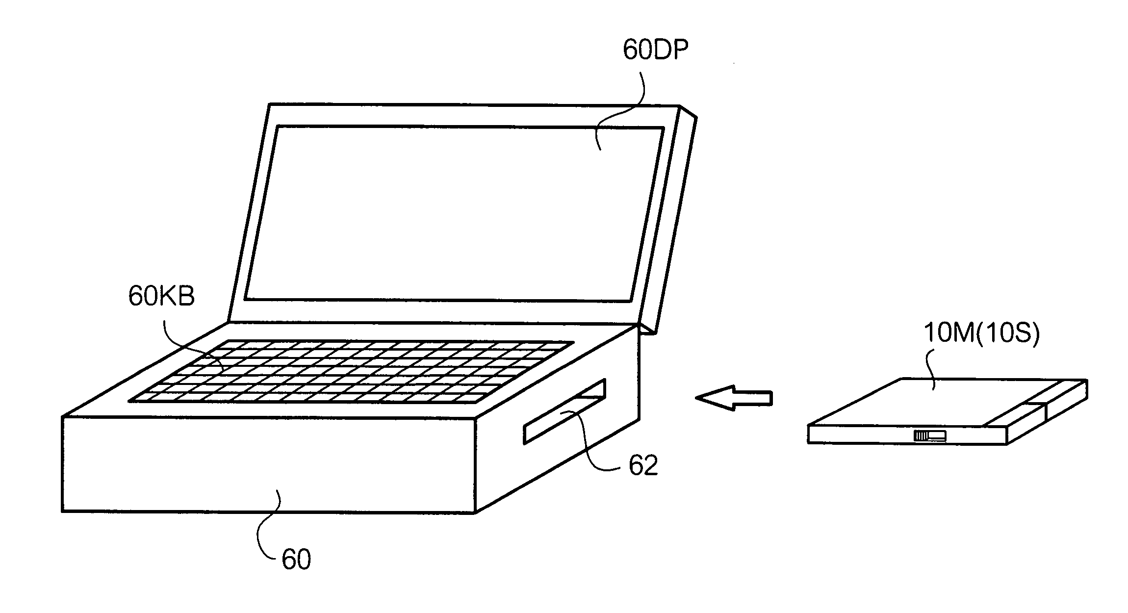
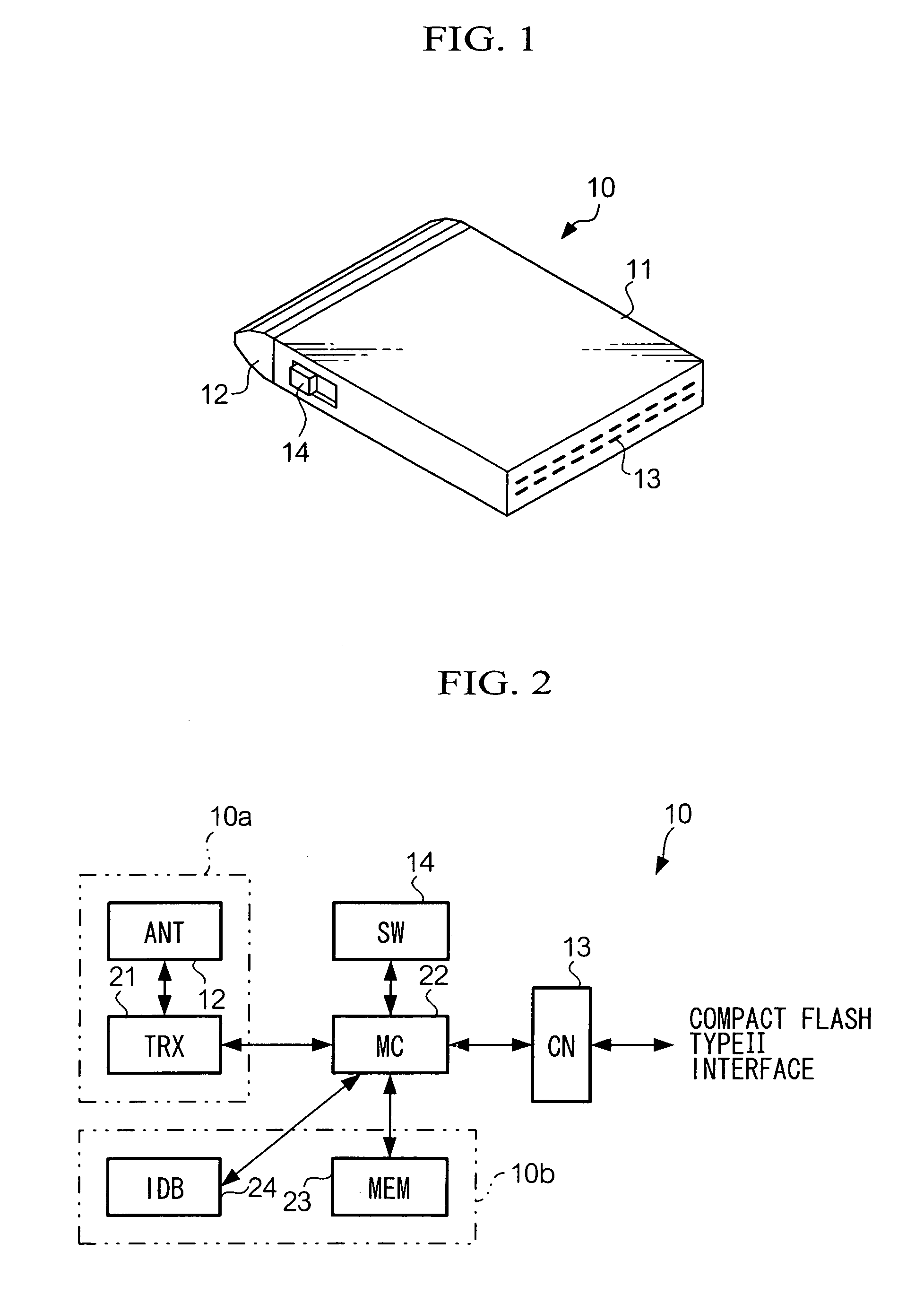
[0082]First, FIG. 1 is an oblique view illustrating the external appearance of a wireless telecommunications unit 10 relating to the first embodiment of the present invention. As shown in the figure, the wireless telecommunications unit 10 is provided with an almost rectangular parallelepiped-shaped housing 11, an antenna 12 and a connector 13 provided to the housing 11, and a mode selection switch 14 provided on the side of the housing 11.
[0083]The wireless telecommunications unit 10 can be used by attaching it to an external unit. The external connector 13 is a connector for attaching the wireless telecommunications unit 10 to an external unit. An external unit is able to perform the processing of wireless telecommunications jointly with the wireless telecommunications unit 10 and the reading / writing of memory data in the wireless telecommunications unit. The external unit can be can be the main...
example 1
A-2-1. EXAMPLE 1
[0117]FIG. 4 is an oblique view showing the wireless telecommunications unit 10 relating to this embodiment and the battery unit 40 and the external unit 60 that can be used therewith. In FIG. 4, the wireless telecommunications unit 10 is of a size that is the same as a small card such as a Compact Flash (registered trademark of Sun Disk Corporation), Smart Media (registered trademark of Toshiba Corporation), Memory Stick (registered trademark of Sony Corporation), Multi Media Card (registered trademark of Siemens A.G.), or a small PC card. The battery unit 40 has a housing 41. In this housing 41 is formed a notched slot 44 that can accommodate the wireless telecommunications unit 10 which is a small card. On the two ends of the slot 44 are provided, respectively, a charging selection switch 45 for switching the charging, and a LED 46 as an indicator for displaying the charging status. At the bottom of the slot 44 is placed a connector 47. When the wireless telecommu...
example 2
A-2-2. EXAMPLE 2
[0127]FIG. 6 is a block diagram illustrating the functional configuration of the second example of the battery unit 40. This battery unit 40 is an improvement on the batter monitor unit 42 in Example 1 above. It should be noted that, in order to impart a deeper understanding of the functional configuration of this battery unit, FIG. 6 shows the small card wireless telecommunications unit 10 and the external unit 60 together with the battery unit 40.
[0128]In FIG. 6, the battery monitor unit 42 has a card power supply means 421 that supplies operating power to the wireless telecommunications unit 10 from the battery 43, and an external unit power supply means 422 that supplies operating power to the external unit 60 from the battery 43, and the charging means 423 that charges the battery 43 from the external unit 60, and the battery voltage detection means 424 that detects the voltage level of the battery 43, and transmits the voltage level signals of the battery 43 to...
PUM
 Abstract
Description
Claims
Application Information